Перейти к содержимому
Machining Graphite Feeds and Speeds: Match the Data to the Tool
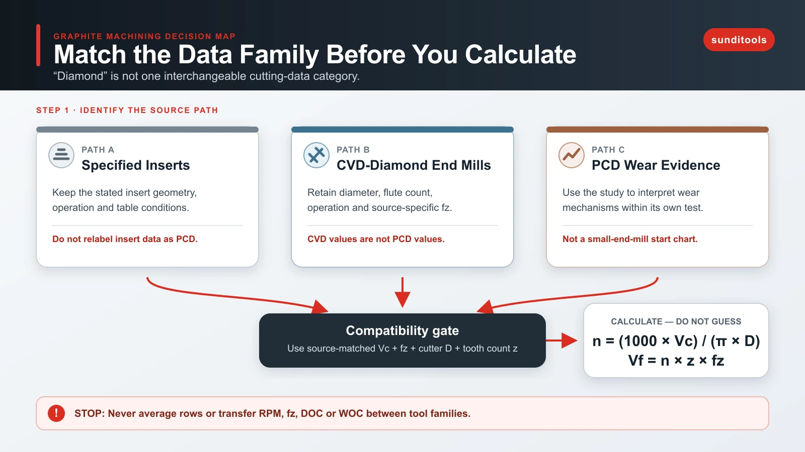
Start by matching the cutting-data family to the tool before calculating RPM. The evidence here follows three separate paths: an IDC table for specified milling inserts, CVD-diamond end-mill data from Decatur and Harvey, and a PCD wear study. They are not interchangeable. In particular, the PCD study explains a failure mechanism but does not provide a transferable PCD start chart.
Once you have a compatible source value for surface speed and feed per tooth, the RPM and table-feed calculations are straightforward. The harder and more important decision is whether the source matches the tool family, diameter, operation, graphite application, engagement, and setup well enough to use at all.
Start with the tool and data family
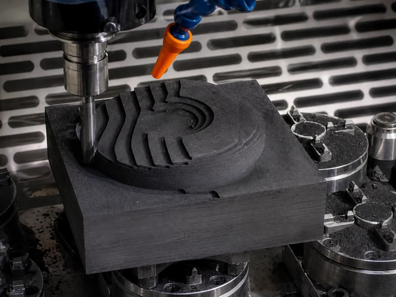
Graphite removes material by brittle fracture, producing powder-like particles rather than metal-like curled chips. It is also abrasive, so rapid edge wear, exit chipping, and dust control belong in the same decision as feeds and speeds. IDC's graphite-and-carbon guidance describes dry machining as the general practice and gives a milling table for inserts with a 0.4-0.8 mm nose radius and at least 10° clearance.
That insert condition matters. It does not identify PCD, end-mill diameter, holder, radial engagement, graphite grade, or machine rigidity. Treat its numbers as insert-table data, not as a graphite-wide default.
Decatur's graphite guide is a separate CVD-diamond end-mill path. It groups starting data by end-mill diameter and general versus finish operation, while noting that grade, setup, and dust-removal practices change actual conditions. Harvey's example is narrower still: a 1/4 in, four-flute CVD-diamond-coated square end mill at 12,000 rpm, 780 SFM, 0.00292 in/tooth, and 140 IPM.
The PCD evidence has a different job. The PCD graphite-mold study used a 1,200 mm cutter with 50 PCD teeth in a 60 rpm, 1,200 mm/min groove test. It documents abrasion and edge-originated cracking or binding-phase failure. It is not a starting table for a small PCD end mill.
Use a source-conditioned starting table
| Data family | Tool and diameter condition | Operation and cited values | Missing or limiting conditions | Use it this way |
|---|---|---|---|---|
| IDC specified inserts | 0.4-0.8 mm nose radius; at least 10° clearance; diameter not stated | General: 100-300 m/min, 0.1 mm/tooth, 5-10 mm DOC. Finish: 150-600 m/min, 0.013-0.05 mm/tooth, 0.5-2 mm DOC. | Graphite grade, holder, rigidity, WOC, and PCD status are not stated. | Use only for a matching insert and operation. Do not relabel it PCD data. |
| Decatur CVD diamond | End mills from 1/64 to 1/2 in, about 0.4-12 mm | At 1/4 in: general 0.002-0.004 in/tooth; finish 0.001-0.002 in/tooth. | EDM-graphite context; no grade, WOC, holder, or rigidity tuple. | Keep the CVD-diamond family and exact diameter/operation. |
| Harvey CVD diamond | 1/4 in, four-flute CVD-diamond-coated square end mill | 12,000 rpm; 780 SFM; 0.00292 in/tooth; 140 IPM. | One vendor example; grade, engagement, rigidity, and PCD applicability are not stated. | Use as a calculation check, not as a setting for another tool family. |
| Thomasnet PCD study | 1,200 mm cutter, 50 PCD teeth | 60 rpm; 1,200 mm/min; 350 mm depth in the reported test. | Large-cutter failure study, not end-mill data. | Use it for bounded PCD wear interpretation only. |
The table gives a practical stop rule: if you cannot match the tool/data family and the stated operating conditions, do not average the rows or convert an RPM from one family into a recommendation for another. For a PCD tool, use a documented compatible PCD Vc и fz input from a qualified tool-data source, then calculate the program values. Current evidence does not authorize a PCD starting range by graphite grade, diameter, finish target, engagement, and rigidity.
Convert compatible inputs to RPM and table feed
Surface speed is peripheral cutting speed. RPM changes when cutter diameter changes, even if surface speed remains the selected input.
Символы: n = частота вращения шпинделя в об/мин; Vc = qualified surface speed in m/min; and D = actual cutting diameter in mm.
The units explain the equation: Vc × 1000 converts m/min to mm/min, and one revolution travels πD mm. Dividing mm/min by mm/rev gives rev/min. This is a geometry conversion, not a way to select Vc. It also assumes that the stated cutter diameter is the relevant cutting diameter.
Table feed follows feed per tooth:
Символы: Vf = table feed in mm/min; n = spindle speed in rev/min; z = number of effective cutting edges engaged per spindle revolution; and fz = feed per tooth in mm/tooth.
The units reduce to mm/min. Use the actual tooth count and the fz from the same compatible source. The formula does not choose fz, DOC, WOC, engagement, or a rigidity correction.
Graphite RPM and Table-Feed Calculator
Use only cutting speed and feed per tooth from one compatible tool-data family. Enter the actual cutter diameter and effective tooth count. The calculator converts the selected inputs; it must not mix insert, CVD-diamond and PCD data.
Conversion only. Preserve tool family, cutter identity, graphite application, engagement, dust removal and setup conditions with the result.
Worked arithmetic check: Harvey’s CVD-diamond example
Harvey states 12,000 rpm, four flutes, 0.00292 in/tooth, and 140 IPM for its specified 1/4 in CVD-diamond-coated tool. The table-feed relationship gives:
Символы: n = 12,000 rpm; z = 4 effective cutting edges (four effective flutes); fz = 0.00292 in/tooth; and Vf = 140.16 in/min table feed.
Rounded to the whole number used in the source, that is 140 IPM. This verifies the arithmetic and units for that stated example. It does not turn 780 SFM or 0.00292 in/tooth into a PCD recommendation.
Adjust after a controlled cut, not by mixing variables
Keep speed, feed per tooth, DOC, WOC, stickout, runout, and dust removal attached to the source and setup. The IDC insert table supplies DOC with its own insert condition. Decatur’s end-mill data use separate diameter and operation rows. Neither supports treating RPM, fz, DOC, and WOC as independent universal settings.
For exit-edge sensitivity, IDC says that limiting exit depth, lowering feed at exit, and chamfering the workpiece can reduce chipping. Decatur also discusses lowering feed at exit and changing the exit strategy. Those are feature and exit-path actions, not a rule to lower the whole program’s feed rate.
Decatur reports that, in its CVD-diamond context, excessively light feed can burnish rather than cut and can accelerate wear. It also warns that short paths with many small adjustments may not reach commanded traverse speed, so calculated chip load can differ from what the path delivers. Use that as a check on the CVD-diamond case. Do not apply its threshold to PCD without compatible PCD evidence.
Diagnose rapid wear and defects before changing a parameter
| Симптом | Evidence-supported possibility | Corrective action and boundary |
|---|---|---|
| Fast, uniform edge wear | Graphite is abrasive; IDC warns that uncoated metallic cutting tools wear quickly. | Inspect the edge, tool family, and dust control before changing a number. |
| Rubbing or burnishing | Decatur links too-light feed with burnishing in its CVD-diamond context. | Check actual fz and path acceleration. Its numerical threshold is not a PCD threshold. |
| Exit chip-out | IDC and Decatur describe exit-feed/depth reduction and chamfer or exit-path changes. | Change the exit condition first, then verify one variable at a time. |
| PCD edge chips or fracture | The PCD study documents edge-originated cracks/voids and binding-phase failure in its large-cutter test. | Inspect edge integrity. Do not diagnose a small PCD mill solely from that test. |
| Dust accumulating in the cut or machine | IDC describes powder-like removal and calls for extraction from the machining region. | Restore extraction before deciding that a feed or speed change is the cause or cure. |
The decision to carry forward
Для generic graphite machining, a usable answer is not one chart. First identify the tool/data family, then retain the source’s diameter, operation, and missing-condition limits, calculate only from compatible inputs, and inspect the symptom before making one controlled change. That keeps a CVD-diamond or insert value from becoming an unsupported PCD setting.
If the next job uses PCD, the appropriate next step is to obtain a PCD-specific condition tuple rather than copy the CVD or insert rows above. For product navigation only, see the PCD milling cutter range.