


Avances et vitesses pour l’usinage du graphite : adapter les données à l’outil
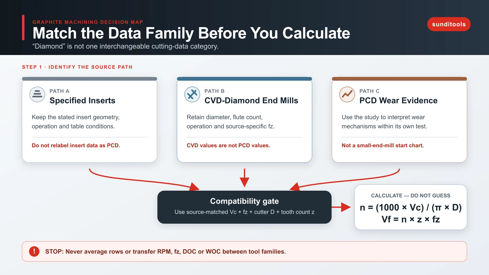
Faites correspondre la famille de données à l’outil avant de calculer les RPM. Les éléments présentés suivent trois voies distinctes : tableau IDC pour des plaquettes définies, données de fraises diamant CVD de Decatur et Harvey, et étude d’usure PCD. Ils ne sont pas interchangeables. L’étude PCD explique notamment un mécanisme de défaillance, sans fournir de tableau initial PCD transférable.
Avec des valeurs compatibles de vitesse périphérique et d’avance par dent, calculer RPM et avance de table est simple. La décision plus difficile et importante est de savoir si la source correspond assez à la famille d’outils, au diamètre, à l’opération, à l’application graphite, à l’engagement et au montage pour être utilisée.
Commencer par la famille d’outils et de données
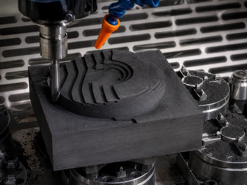
Le graphite s’enlève par rupture fragile, produisant des particules poudreuses plutôt que des copeaux métalliques courbés. Il est abrasif : usure rapide, écaillage en sortie et maîtrise des poussières doivent accompagner le choix des paramètres. Le guide IDC décrit l’usinage à sec comme pratique générale et donne un tableau pour des plaquettes de rayon de bec 0.4-0.8 mm et de dépouille d’au moins 10°.
Cette condition de plaquette compte. Elle ne précise ni PCD, ni diamètre de fraise, ni porte-outil, engagement radial, nuance de graphite ou rigidité. Traitez ces chiffres comme des données de plaquettes, pas comme des valeurs générales pour le graphite.
Le guide Decatur suit une voie distincte pour les fraises diamant CVD. Il classe les données initiales par diamètre et opération générale ou finition, en précisant que nuance, montage et dépoussiérage modifient les conditions. L’exemple Harvey est plus restreint : fraise à bout plat revêtue diamant CVD de 1/4 pouce, quatre dents, à 12,000 rpm, 780 SFM, 0.00292 pouce/dent et 140 IPM.
Les données PCD ont un autre rôle. L’étude PCD de moules en graphite utilisait une fraise de 1,200 mm à 50 dents PCD dans un essai de rainurage à 60 rpm et 1,200 mm/min. Elle documente abrasion, fissures partant de l’arête ou défaillance du liant. Ce n’est pas un tableau initial pour petite fraise PCD.
Utiliser un tableau initial conditionné par sa source
| Famille de données | Condition d’outil et de diamètre | Opération et valeurs citées | Conditions manquantes ou limitantes | Utilisation appropriée |
|---|---|---|---|---|
| Plaquettes spécifiées par IDC | Rayon 0.4-0.8 mm ; dépouille d’au moins 10° ; diamètre non précisé | Général : 100-300 m/min, 0.1 mm/dent, 5-10 mm DOC. Finition : 150-600 m/min, 0.013-0.05 mm/dent, 0.5-2 mm DOC. | Nuance de graphite, porte-outil, rigidité, WOC et statut PCD non précisés. | Utiliser seulement pour une plaquette et une opération compatibles. Ne pas les rebaptiser données PCD. |
| Diamant CVD Decatur | Fraises de 1/64 à 1/2 pouce, environ 0.4-12 mm | À 1/4 pouce : général 0.002-0.004 pouce/dent ; finition 0.001-0.002 pouce/dent. | Contexte graphite EDM ; pas d’ensemble précisant nuance, WOC, porte-outil ou rigidité. | Conserver la famille diamant CVD et le diamètre/l’opération exacts. |
| Diamant CVD Harvey | Fraise à bout plat revêtue diamant CVD de 1/4 pouce, quatre dents | 12,000 rpm ; 780 SFM ; 0.00292 pouce/dent ; 140 IPM. | Un exemple fournisseur ; nuance, engagement, rigidité et applicabilité au PCD non précisés. | Utiliser pour vérifier le calcul, non comme réglage d’une autre famille d’outils. |
| Étude PCD Thomasnet | Fraise de 1,200 mm, 50 dents PCD | 60 rpm ; 1,200 mm/min ; profondeur de 350 mm dans l’essai rapporté. | Étude de défaillance d’une grande fraise, pas de données de fraise en bout. | Utiliser seulement pour une interprétation encadrée de l’usure PCD. |
Le tableau fournit une règle d’arrêt : si famille d’outils/de données et conditions indiquées ne correspondent pas, ne faites pas de moyenne entre les lignes et ne transposez pas les RPM d’une famille à une autre. Pour un outil PCD, utilisez une donnée PCD documentée et compatible de Vc et fz provenant d’une source qualifiée de données d’outils, puis calculez les valeurs du programme. Les données actuelles ne justifient pas une plage initiale PCD selon nuance de graphite, diamètre, objectif de finition, engagement et rigidité.
Convertir les données compatibles en RPM et avance de table
La vitesse de surface est la vitesse de coupe périphérique. Les RPM changent avec le diamètre, même si la vitesse périphérique sélectionnée reste identique.
Symboles : n = régime de broche en rpm ; Vc = vitesse périphérique validée en m/min ; et D = diamètre de coupe réel en mm.
Les unités expliquent l’équation : Vc × 1000 convertit les m/min en mm/min, et un tour parcourt πD mm. Diviser mm/min par mm/tour donne tours/min. C’est une conversion géométrique, pas une méthode de choix de Vc. Le diamètre indiqué doit aussi être le diamètre de coupe pertinent.
L’avance de table découle de l’avance par dent :
Symboles : Vf = avance de table en mm/min ; n = régime de broche en tours/min ; z = nombre d’arêtes effectives engagées par tour de broche ; et fz = avance par dent en mm/dent.
Les unités se réduisent à mm/min. Utilisez le nombre réel de dents et la valeur de fz de la même source compatible. La formule ne choisit ni fz, ni DOC, ni WOC, ni engagement, ni correction de rigidité.
Calculateur de RPM et d’avance de table pour le graphite
Utilisez vitesse et avance par dent d’une même famille compatible. Saisissez diamètre réel et nombre de dents effectives. Le calculateur convertit les données choisies ; il ne doit pas mélanger plaquettes, diamant CVD et PCD.
Conversion uniquement. Conserver famille, identité d’outil, application graphite, engagement, dépoussiérage et montage avec le résultat.
Vérification arithmétique : exemple diamant CVD de Harvey
Harvey indique 12,000 rpm, quatre dents, 0.00292 pouce/dent et 140 IPM pour son outil de 1/4 pouce revêtu diamant CVD. La relation d’avance donne :
Symboles : n = 12,000 rpm; z = 4 arêtes effectives (quatre goujures effectives) ; fz = 0.00292 pouce/dent ; et Vf = 140.16 pouces/min d’avance de table.
Arrondi à l’entier utilisé par la source, cela donne 140 IPM. Le calcul et les unités de cet exemple sont vérifiés, sans transformer 780 SFM ou 0.00292 pouce/dent en recommandation PCD.
Ajuster après une coupe contrôlée sans mélanger les variables
Gardez vitesse, avance par dent, DOC, WOC, porte-à-faux, faux-rond et dépoussiérage liés à la source et au montage. Le tableau IDC donne DOC pour ses propres plaquettes. Les données Decatur séparent diamètres et opérations. Aucun ne justifie des RPM, fz, DOC et WOC universels et indépendants.
Pour les arêtes de sortie sensibles, IDC indique que limiter la profondeur, réduire l’avance en sortie et chanfreiner la pièce peuvent réduire l’écaillage. Decatur évoque aussi la réduction d’avance et une autre stratégie de sortie. Ces actions concernent la forme et la sortie, pas une baisse générale de l’avance du programme.
Decatur rapporte que, dans son contexte diamant CVD, une avance trop faible peut brunir plutôt que couper et accélérer l’usure. Les trajets courts à nombreuses corrections peuvent ne pas atteindre la vitesse commandée ; la charge calculée diffère alors de celle réellement produite. Utilisez ce contrôle pour le diamant CVD, sans transposer son seuil au PCD sans données PCD compatibles.
Diagnostiquer usure rapide et défauts avant de changer un paramètre
| Symptôme | Possibilité étayée par les données | Action corrective et limites |
|---|---|---|
| Usure rapide et uniforme de l’arête | Le graphite est abrasif ; IDC avertit de l’usure rapide des outils métalliques non revêtus. | Inspecter arête, famille d’outils et dépoussiérage avant de changer une valeur. |
| Frottement ou brunissage | Decatur associe avance trop faible et brunissage dans son contexte diamant CVD. | Vérifier fz réel et accélération de trajectoire. Ce seuil numérique n’est pas un seuil PCD. |
| Écaillage en sortie | IDC et Decatur décrivent réduction d’avance/profondeur en sortie et changements de chanfrein ou de trajectoire. | Modifier d’abord la sortie, puis vérifier une variable à la fois. |
| Écaillage ou fracture d’arête PCD | L’étude PCD documente fissures/vides partant de l’arête et défaillance du liant sur sa grande fraise. | Inspecter l’intégrité de l’arête. Ne pas diagnostiquer une petite fraise PCD sur ce seul essai. |
| Poussière accumulée dans la coupe ou la machine | IDC décrit l’enlèvement poudreux et demande une aspiration dans la zone d’usinage. | Rétablir l’aspiration avant d’attribuer cause ou solution à l’avance ou au régime. |
La décision à retenir pour la suite
pour l’usinage général du graphite, une seule table ne suffit pas. Identifiez la famille, conservez diamètre, opération et limites de la source, calculez seulement avec des données compatibles et inspectez le symptôme avant une modification contrôlée. Cela évite de transformer une valeur diamant CVD ou de plaquette en réglage PCD non étayé.
Si le prochain travail utilise du PCD, obtenez un ensemble de conditions propres au PCD au lieu de copier les lignes CVD ou plaquettes ci-dessus. Pour la navigation produits uniquement, consultez la gamme de fraises PCD.