Перейти к содержимому
Скорости и подачи при развертывании: рассчитайте, а затем проверьте качество реза
Настройки скорости и подачи развертки Это пятиэтапная процедура: определение значений скорости резания и подачи для конкретного инструмента и условий обработки, определение единиц измерения, расчет числа оборотов в минуту, расчет линейной подачи и проверка правильности команды в ходе контролируемой резки. Калькулятор может выполнить промежуточные этапы. Однако он не может определить, соответствуют ли исходные данные развертке, обрабатываемому материалу, исходному отверстию, припуску, системе смазки, держателю, станку и требованиям к отверстию.
Это различие позволяет избежать двух дорогостоящих ошибок. Первая — ввод математически правильного значения числа оборотов в минуту (RPM) на основе таблицы материалов, не имеющей отношения к данному случаю. Вторая — путаница между подачей за оборот и подачей на зуб или линейной подачей. В обоих случаях получаются команды, которые выглядят точными, но имеют неверное физическое значение.
Используйте эту статью в качестве рабочего листа для расчетов и выпуска продукции. В ней намеренно не приводится единая универсальная таблица материалов: решение должно основываться на данных, относящихся к конкретному инструменту, и результатах измерений технологического процесса.
Создайте вводный лист перед тем, как открыть калькулятор
Не начинайте с значения RPM. Начните с кортежа условий, указанного после данных о резании. Если один из следующих входных параметров неизвестен, вычисленная команда будет иметь предварительный характер.
| Обязательные поля | Утвержденный источник или измерение | Почему это влияет на результат |
|---|---|---|
| Точные характеристики развертки и материал режущей кромки | Чертеж инструмента, этикетка, отчет о закупках, данные о поставщике | Геометрия, материал кромки, покрытие и класс применения определяют допустимые исходные данные |
| Фактический диаметр реза | Чертеж инструмента и проверенный метод измерения | Число оборотов в минуту изменяется обратно пропорционально диаметру |
| Материал и состояние изделия | Сертификат на материал, чертеж, протокол измерения твердости или протокол термообработки | Обрабатываемость, адгезия, износостойкость и упрочнение при обработке влияют на скорость резания и подачу |
| Тип отверстия, глубина и перерывы | Чертеж детали и траектория инструмента | Слепые, сквозные, глубокие и прерывистые отверстия влияют на состояние стружки и охлаждающей жидкости |
| Припуск на отверстие и припуск на заготовку | Расчетные параметры исходного отверстия и утвержденный технологический план | Расширитель должен снимать контролируемый объём материала, а не просто тереть или удалять избыточный материал |
| Охлаждающая жидкость или смазочное вещество и траектория движения стружки | Фактическая настройка оборудования | Смазывание, охлаждение и отвод отходов влияют на состояние режущей кромки и качество поверхности внутренней поверхности |
| Держатель, выступ, выравнивание и биение | Инструкция по настройке и схема сборки | Неравномерная нагрузка на кромки может оказывать доминирующее влияние на регулировку подачи или скорости |
| Число оборотов станка и диапазон подачи | Техническая документация на оборудование и текущие настройки | Рассчитанные команды должны быть исполняемыми и устойчивыми при нагрузке |
| Допуск на отверстие и метод контроля | Чертеж и план обеспечения качества | Для проверки реза необходимо определить признаки отрыва |
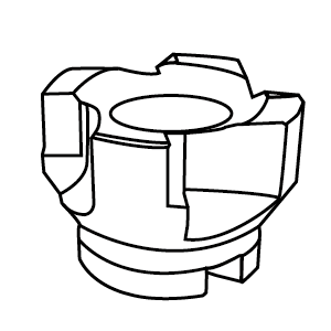
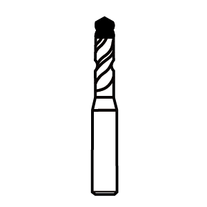
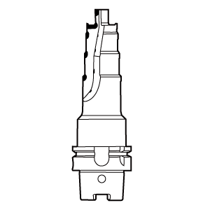
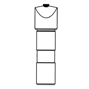
Выбирать семейство инструментов следует только после того, как будут известны материал, диаметр, допуск, геометрия отверстия и тип станка. Развёртки PCD служит ориентиром для выбора подходящих семейств PCD; данная таблица не является таблицей режущих данных и не подтверждает, что PCD подходит для любого обрабатываемого материала. Перед программированием необходимо получить актуальные данные по применению выбранной модели.
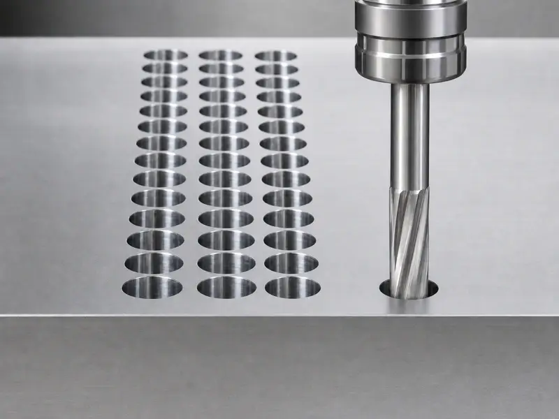
Расширивание — это операция чистовой обработки. Она позволяет увеличить существующее отверстие на заданную величину и обычно применяется для улучшения размеров и качества поверхности. Эта операция не заменяет определение требуемого положения отверстия или исправление значительных погрешностей прямолинейности. В обзоре «CNC Cookbook», посвящённом скоростям вращения разверток, подачам и подготовке отверстий, проводится такое же разграничение процессов: подготовленное отверстие и условия обработки остаются частью конечного результата.
Выясните, что означает номер канала
Прежде чем приступить к вычислениям, ознакомьтесь с заголовком столбца в каталоге и указанной в нём единицей измерения. Чаще всего путают три величины подачи.
Подача за оборот описывает осевой ход за один оборот шпинделя. Его можно обозначить как IPR, дюймы/об., мм/об. или f_rev. Когда поставщик разверток указывает это значение, рассчитайте линейную подачу, умножив его на число оборотов в минуту:
Линейная подача = число оборотов в минуту × подача за оборот
Подача на зуб описывает подачу, выделенную на каждую режущую кромку. Она может обозначаться как IPT, дюймы на зуб, мм на зуб или f_z. Только в том случае, если в источнике явно указана подача на зуб, количество канавок следует учитывать при пересчете:
Линейная подача = число оборотов в минуту × количество действующих зубьев × подача на зуб
Линейная подача — это команда осевой подачи станка, обычно выражаемая в единицах IPM, дюймов/мин, мм/мин или F. Это уже расстояние в минуту. Не умножайте его снова на число оборотов в минуту.
Эта единица измерения имеет важное значение, поскольку во многих наборах данных по разверткам используется подача за оборот, тогда как в документации по фрезерованию часто указывается подача на зуб. Наличие шести канавок у развертки не означает, что значение IPR следует умножать на шесть. Такой подход приводит к изменению заданной подачи на коэффициент, который никогда не фигурировал в определении поставщика.
Аналогичным образом, значение IPM или мм/мин нельзя скопировать из другой настройки без указания числа оборотов в минуту (RPM), при котором оно было получено. Если частота вращения шпинделя изменяется, а заданная подача за оборот должна оставаться постоянной, линейная подача должна изменяться в той же пропорции.
Обсуждение в магазине, прошедшее экспертную проверку, на тему Параметры подачи и скорости вращения расточного станка с ЧПУ Это иллюстрирует существующую на практике путаницу. Авторы предлагают разные соотношения сверления, скорости по поверхности, подачи и припуски, поскольку у них разные инструменты, материалы и опыт. Из этого можно извлечь следующий урок: необходимо определить источник данных и единицы измерения, а затем провести испытания в реальных условиях — а не усреднять ответы и составлять на их основе новую таблицу.
Интерактивный калькулятор начальной точки
Рассчитать частоту вращения развертки и подачу стола
Введите утвержденную скорость резания, диаметр развертки и подачу за оборот. Используйте полученный результат в качестве отправной точки для контролируемого пробного запуска, а затем проведите квалификацию отверстия.
Частота вращения шпинделя
2,228RPM
Подача стола
334мм/мин
RPM = (1 000 × Vc) ÷ (π × D) · Подача стола = обороты в минуту × частота колебаний на оборот
Значение π установлено на 3,14159. Перед утверждением настроек для серийного производства необходимо проверить предварительное отверстие, припуск, биение патрона, подачу охлаждающей жидкости и измеренный диаметр отверстия.
Рассчитать частоту вращения шпинделя по скорости резания
Скорость резания — это тангенциальная скорость режущей кромки на уровне диаметра инструмента. При одинаковой скорости резания развертка меньшего диаметра должна вращаться быстрее, чем развертка большего диаметра.
В каталогах с дюймовыми единицами измерения эта величина часто называется скорость по поверхности и выражается в SFM. В метрических каталогах скорость резания обычно указывается в метрах в минуту. Физическая зависимость остается той же, однако числовое значение и коэффициент пересчёта зависят от системы единиц измерения.
Для дюймовой системы мер, когда скорость резания указана в поверхностных футах в минуту, а диаметр — в дюймах:
RPM = (SFM × 12) ÷ (π × диаметр в дюймах)
Приближение «магазина» Обороты в минуту = (SFM × 3,82) ÷ диаметр в дюймах использует 12 ÷ π ≈ 3,82. Сохраните достаточную точность для вычислений, а затем округлите результат до формата, который может обработать компьютер.
Для метрической системы единиц, когда скорость резания указана в метрах в минуту, а диаметр — в миллиметрах:
RPM = (скорость резания в м/мин × 1000) ÷ (π × диаметр в мм)
Преобразования носят геометрический характер. Сложным входным параметром является скорость резания. Уточняйте её у выбранного поставщика разверток с учётом условий, соответствующих режущему материалу, группе и состоянию заготовки, режиму подачи охлаждающей жидкости, типу отверстия и области применения. Значение, обозначенное как “твердый сплав”, не всегда подходит для всех марок или геометрий твердого сплава; названия семейства материалов недостаточно, если твёрдость или термообработка существенно влияют на обрабатываемость.
Перед нажатием кнопки «Рассчитать» проверьте сочетание единиц измерения. Ввод метрического диаметра в формулу с дюймами, использование показателя «метры в минуту» вместо SFM или ввод номинального размера отверстия в случае, когда поставщик определяет другой эффективный диаметр, приводит к значительной погрешности, при этом калькулятор не выдает предупреждения.
Рассчитать линейный ход по значению хода за один оборот
Как только станет известна частота вращения (RPM), преобразуйте значение подачи, указанное поставщиком на один оборот, в команду подачи станка.
Для дюймовых единиц измерения:
Подача в IPM = RPM × подача в IPR
Для метрических единиц измерения:
Питание в мм/мин = число оборотов в минуту × питание в мм/об
Проверка размеров является полезной:
об/мин × длина/об = длина/мин
Обращения взаимно компенсируются, в результате чего остается правильная единица линейной подачи. Если единицы измерения не компенсируются полностью, остановите процесс и приведите их к единой системе отсчёта перед началом программирования.
Если поставщик действительно указывает подачу на зуб, используйте количество эффективных режущих зубьев, определённое для данного инструмента и условий применения:
Подача = число оборотов в минуту × количество эффективных зубьев × подача на зуб
Не следует полагать, что количество видимых канавок и эффективное количество зубьев всегда взаимозаменяемы. Конструкция угла наклона, неравномерное расстояние между зубьями, направляющие элементы и специальные геометрические формы могут сделать общее допущение о количестве зубьев неуместным. Окончательное определение содержится в технических данных инструмента.
Рассмотрим один наглядный пример с метрикой
Предположим, что выбранный поставщик разверток указал гипотетические исходные значения: скорость резания 60 м/мин и подачу 0,20 мм/об для конкретного инструмента диаметром 10 мм при полностью подходящих условиях применения. Эти цифры приведены исключительно в качестве примера; они не являются рекомендациями в отношении материала или инструмента SCT.
Сначала рассчитайте число оборотов в минуту:
RPM = (60 × 1000) ÷ (π × 10)
Число оборотов в минуту ≈ 1909,9
Округлите значение до значения, при котором можно запустить процесс, например до 1910 об/мин, если это позволяют возможности оборудования и технологического процесса.
Затем рассчитайте линейную подачу:
Подача = 1910 × 0,20
Скорость подачи = 382 мм/мин
Запишите как результат вычисления без округления, так и заданные значения. Если система управления допускает только иной шаг изменения числа оборотов, пересчитайте подачу исходя из фактического числа оборотов, а не оставляйте значение 382 мм/мин без изменений.
Например, если фактическая команда составляет 1800 об/мин:
Подача = 1800 × 0,20 = 360 мм/мин
Соотношение 0,20 мм/об., предусмотренное в задании, сохраняется. В этом и заключается основная функция калькулятора скорости и подачи развертки: правильное преобразование единиц измерения и выполнение арифметических вычислений. Калькулятор не проверяет правильность введенных значений 60 м/мин или 0,20 мм/об.
Пересчитать, если система не может обработать результат
Ограничение, связанное с оборудованием, изменяет выполняемую команду. Оно не должно без предупреждения изменять выбранную зависимость подачи.
Если рассчитанная частота вращения превышает допустимый предел для шпинделя, установите достижимую частоту вращения и пересчитайте линейную подачу исходя из заданной подачи на оборот. Если шпиндель не может стабильно работать при очень низкой рассчитанной частоте вращения, проанализируйте поведение станка под нагрузкой и целесообразность данной комбинации инструмента и технологического процесса, а не повышайте частоту вращения без пересмотра скорости резания.
Применяйте ту же дисциплину к ограничениям подачи. Если система управления, ось, встроенный цикл или настройки не позволяют плавно обеспечить рассчитанную линейную подачу, простое уменьшение подачи приводит к снижению подачи за оборот. Это может изменить характер взаимодействия режущей кромки с заготовкой с резания на трение. Правильным решением может быть использование другой пары «скорость резания/подача», одобренной поставщиком инструмента, другого инструмента или другого станка — а не несогласованной пары команд.
Переопределения также требуют контроля. Переопределение скорости шпинделя без пропорционального изменения подачи изменяет подачу на оборот. Переопределение подачи без изменения скорости шпинделя приводит к тому же результату. Во время проверочных испытаний следует фиксировать значения обоих переопределений в процентах и рассчитать фактическую зависимость, прежде чем делать вывод об улучшении технологического процесса.
Проверьте мощность, крутящий момент, грузоподъемность держателя, подачу охлаждающей жидкости и закрепление заготовки в режиме реального управления. Тот факт, что система управления принимает заданное значение, еще не означает, что механическая система способна его выдержать.
Удерживайте сопеременные в неизменном положении во время пробной резки
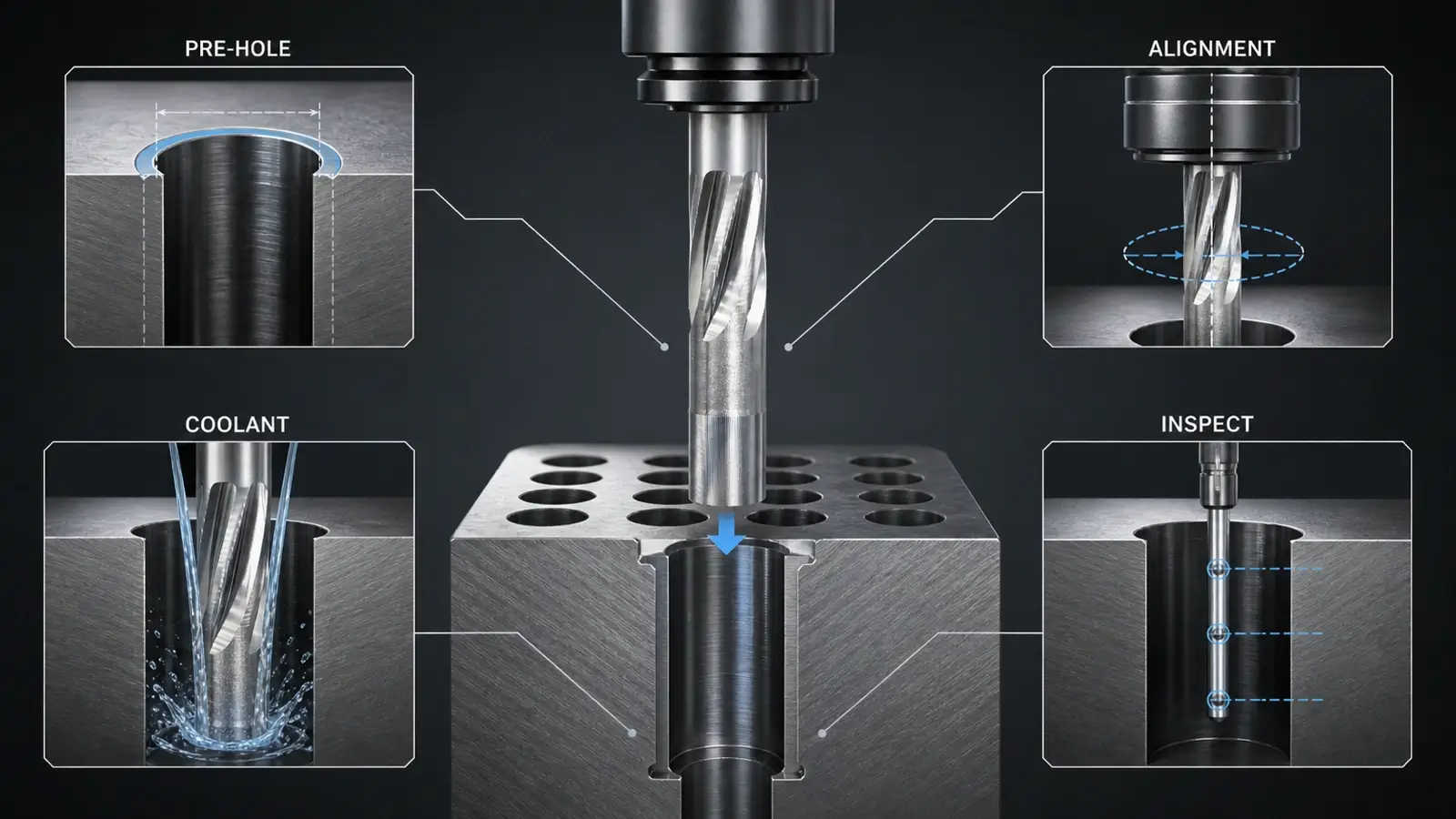
При первом проходе можно проверить только те параметры, которые остаются под контролем. Перед развертыванием измерьте предварительно просверленное отверстие. При необходимости проверьте размеры по глубине, прямолинейности или положению оси, а также округлость, фаску на входе и качество поверхности. Запишите фактический припуск на обработку, а не только номинальный размер сверла.
Слишком большой зазор может привести к увеличению режущего усилия, нагрева и прогиба. Слишком малый зазор может вызвать прерывистый контакт или трение. Допустимое значение зависит от диаметра, конструкции инструмента, обрабатываемого материала, качества предварительно просверленного отверстия и условий обработки. Руководствуйтесь данными выбранного инструмента, а не принимайте за правило процентные значения или фиксированные величины зазора, взятые из других источников.
Определите размеры собранной системы «шпиндель-держатель-развертка» в соответствии с утвержденной методикой измерения. Очистите соединительные поверхности, проверьте вылет и убедитесь в правильном выравнивании. Биение может привести к тому, что на одну кромку будет приходиться непропорционально большая нагрузка, поэтому изменение запрограммированной подачи может устранить симптом, не устранив при этом механическую причину.
Убедитесь, что охлаждающая жидкость или смазочное вещество поступает к режущему элементу и что для стружки предусмотрен канал, соответствующий типу сквозного или глухого отверстия. Проверьте цикл входа и выхода, в том числе уточните, допускает ли поставщик остановку шпинделя, реверс или использование конкретного метода отвода. Перед испытанием осмотрите развертку, чтобы можно было отличить новые следы износа или нагар от ранее имевшихся повреждений.
Необходимо поддерживать постоянными следующие параметры: партия и состояние заготовки, станок, зажимное устройство, инструмент, траекторию предварительного сверления, состояние охлаждающей жидкости, версию программы и метод контроля. В противном случае в ходе испытания будет сравниваться совокупность технологических параметров, а не изменение одного конкретного параметра.
Определите начальную точку относительно отверстия и инструмента
По возможности выполните первую пробную резку на тестовом элементе или заготовке, предназначенной для утилизации. Не используйте в качестве объекта проверки калькулятора дорогостоящий серийный элемент.
- Проверьте предварительно просверленное отверстие и зафиксируйте припуск на заготовку.
- Проверьте инструмент, держатель, биение, подачу охлаждающей жидкости и идентификатор программы.
- Запустите расчётную частоту вращения и подачу без незарегистрированных отклонений.
- Измерьте диаметр проходного отверстия на входе, в середине и на выходе или в нижней части, в различных положениях, если это допускает применяемый метод контроля.
- Укажите характеристики конусности, раструба, округлости или расположения, предусмотренные чертежом.
- Оцените качество обработки поверхности, следы от инструмента и наличие стружки.
- Регистрируйте нагрузку на шпиндель, шум, вибрацию, динамику изменения температуры и состояние режущей кромки.
- Повторите достаточное количество измерений, чтобы отличить стабильный процесс от единичного благоприятного результата.
Отверстие и инструмент необходимо рассматривать в совокупности. Гладкое отверстие с постоянным превышением номинального размера дает иные результаты при исследовании, чем следы вибрации, конусность, раструб на входе, быстрый износ кромок или отклонения от номинала от детали к детали. Одно лишь качество поверхности не является доказательством соответствия размеру, а показания диаметра сами по себе могут скрывать конусность или неравномерность поверхности.
Перед началом испытания определите допустимые пределы: допустимые размеры и геометрию, требования к поверхности, повторяемость, поведение под нагрузкой, условия на кромках и пределы вмешательства. Без таких пределов операторы могут продолжать корректировку до тех пор, пока одно из измерений не покажет удовлетворительный результат.
Изменяйте какой-либо параметр только в том случае, если это подтверждается фактическими данными
Шлифованные или полированные кромки: Сначала убедитесь, что запас материала достаточен и непрерывен, что направочное отверстие находится в надлежащем состоянии, а кромка острая и чистая. Если все эти условия соблюдены, а данные указывают на неэффективность резания, выполните одно целенаправленное изменение подачи или скорости. Ожидайте изменения следов резания и температурного поведения, а также стабильности размеров; в противном случае вернитесь к схеме поиска причин.
Шум или периодический рисунок на поверхности: Перед выполнением команд редактирования проверьте биение в сборе, центрирование, вылет, держатель, зажимное приспособление, предварительное отверстие и прерывистые элементы. Если механическая система прошла проверку, протестируйте одно изменение, рекомендованное поставщиком, и зафиксируйте, как на это реагируют вибрация, шум и периодичность поверхности. Одновременное уменьшение всех параметров может привести к смещению вибрации без определения стабильного диапазона.
Нестандартный размер, коническая форма или раструб: Проведите калибровку измерительного прибора, составьте карту внутреннего диаметра с указанием глубины и ориентации, сравните её с картой, составленной до начала бурения, и проверьте центрирование и биение. Не следует полагать, что снижение частоты вращения устранит геометрические отклонения, возникшие в результате бурения, или неправильное центрирование входного отверстия. Изменяйте параметры резания только после того, как будут выполнены все проверки по механической и измерительной частям.
Быстрый износ, нагрев или наслоение на кромках: Уточните материал и твердость заготовки, тип инструмента, концентрацию охлаждающей жидкости или смазочного материала, подачу на режущую кромку, припуск и отвод стружки. Если заданная скорость резания выходит за пределы диапазона, указанного в технических характеристиках выбранного инструмента, устраните эту ошибку и повторите проверку. Если при использовании утвержденных настроек по-прежнему наблюдается прилипание или абразивный износ, возможно, следует пересмотреть выбор материала или геометрии инструмента.
Чипы с уплотненной поверхностью или с насечками: Проверьте тип отверстия, направление канавки, траекторию подачи охлаждающей жидкости, глубину и отвод. Изменение подачи не может создать траекторию выхода, которой нет в настройках. Сначала исправьте условия выхода; затем настройте подачу в соответствии с данными выбранного инструмента.
Каждая корректировка должна сопровождаться прогнозом. Укажите, какие показатели, как ожидается, улучшатся, измените одну переменную, повторите ту же последовательность измерений и сравните результаты с исходными данными. Если прогнозируемый результат не наблюдается, восстановите контролируемые исходные условия, прежде чем проверять другую гипотезу.
Заблокировать запись о квалифицированном процессе
В предоставленной документации по процессу развертывания должно быть указано, откуда взято каждое число. Укажите поставщика инструмента и версию документации, точную идентификацию инструмента, материал заготовки и его состояние, скорость резания, определение подачи и единицы измерения, формулы, использованный диаметр, неокруглённый результат, запрограммированные обороты и подачу, ограничения станка, переопределения, предварительное отверстие и припуск, результат проверки держателя/биения, состояние охлаждающей жидкости и данные проверки.
Кроме того, следует фиксировать допустимые рабочие параметры и условия остановки: изменение размеров, изменение поверхности, изменение нагрузки или вибрации, износ кромок, поведение стружки, количество инструментов и требуемую периодичность контроля. Это позволяет превратить успешную пробную резку в воспроизводимый производственный стандарт.
Окончательные команды — это не просто результаты вычислений калькулятора. Они представляют собой совокупность проверенных данных инструмента, арифметических вычислений с учетом допусков единицы измерения, допустимых пределов станка и данных, полученных при сверлении реального отверстия. Сохраните все четыре компонента, и при следующей настройке можно будет воспроизвести ход рассуждений, а не гадать, выбирая два числа.