Перейти к содержимому
Reaming surface finish problems: diagnose chatter, runout, feed marks, and built-up edge
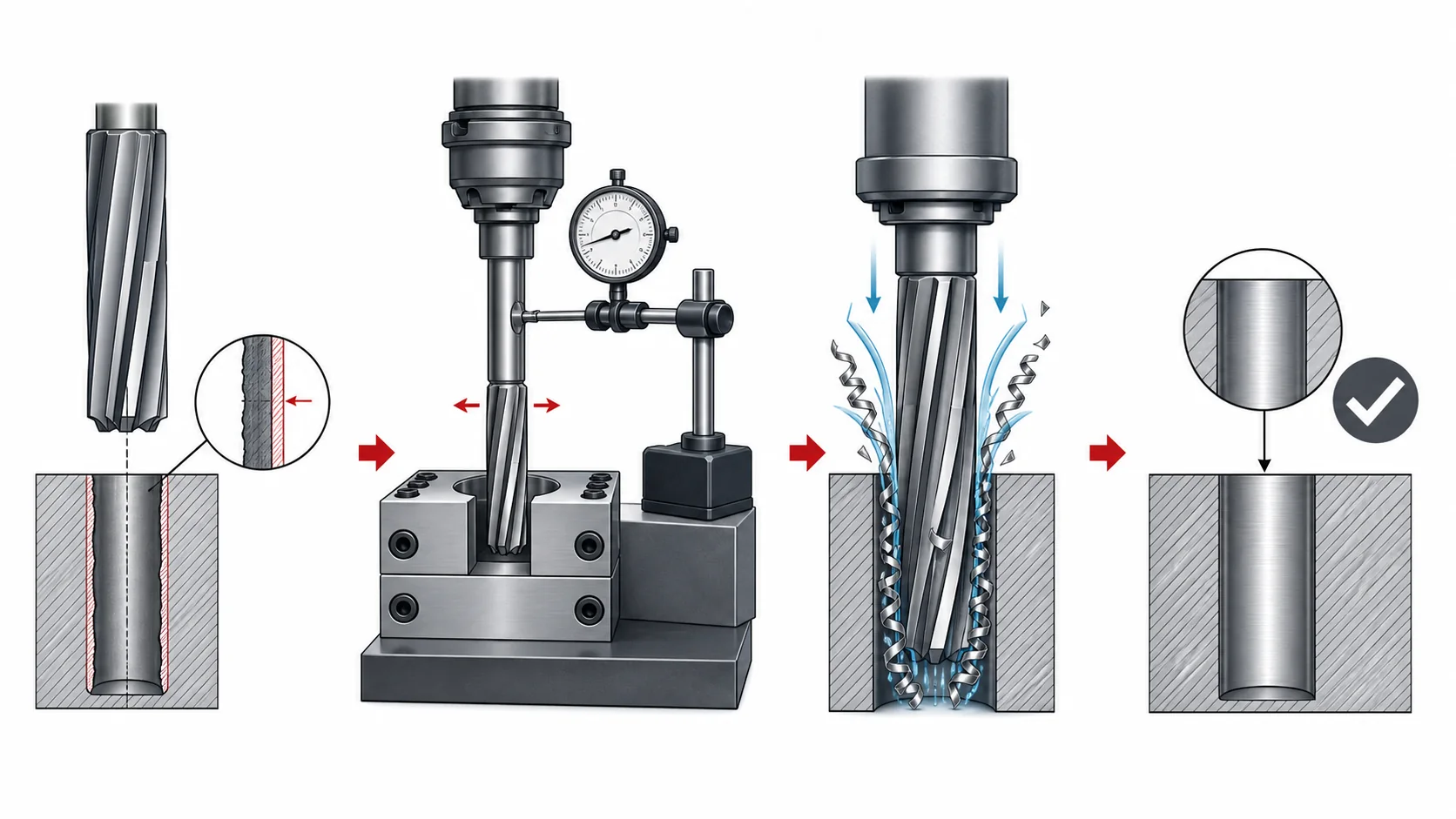
A poor reaming surface finish is easy to blame on speed or feed because the defect appears during the reaming pass. That is often the wrong first move. A reamer follows the hole it receives, so the prehole, remaining stock, alignment, and setup can determine whether its cutting chamfers can produce a clean finish.
Start with a simple question: did the process create a good hole for this reamer to finish? If the answer is uncertain, changing a parameter may hide the useful evidence.
Start with the hole that the reamer receives
Confirm the drilled or bored hole before inspecting the reamer. Record the actual material, hole type, depth, measured prehole size, and how the remaining stock was defined. That last point matters. A number can refer to radial or diametral stock, and values expressed as an inch allowance cannot be exchanged casually for a percentage.
Also look at the hole path and entry condition. A reamer tends to follow the existing hole rather than correct a large location or straightness error. If the upstream operation walked, a finish-only adjustment is not a reliable repair. The first useful correction may be in drilling, boring, fixturing, or alignment.
Too little stock can leave the tool rubbing instead of cutting. Too much can overload the cutting chamfers. Both can show up as a poor finish, but they call for a measurement and a tool-specific decision, not a guess.
Read the finish before changing a parameter
The visible pattern should decide the first inspection branch. Super Tool’s troubleshooting table separates unequal chamfers, incorrect margins, excessive spindle runout, chatter, and insufficient cutting action. Treat those as different possibilities, even when the surface looks generally rough.
Repeating marks: inspect runout, holding, and rigidity
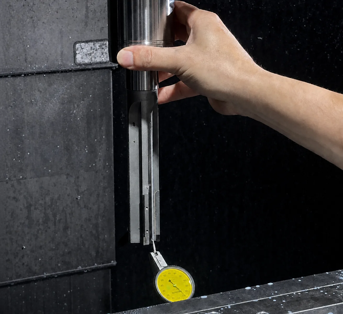
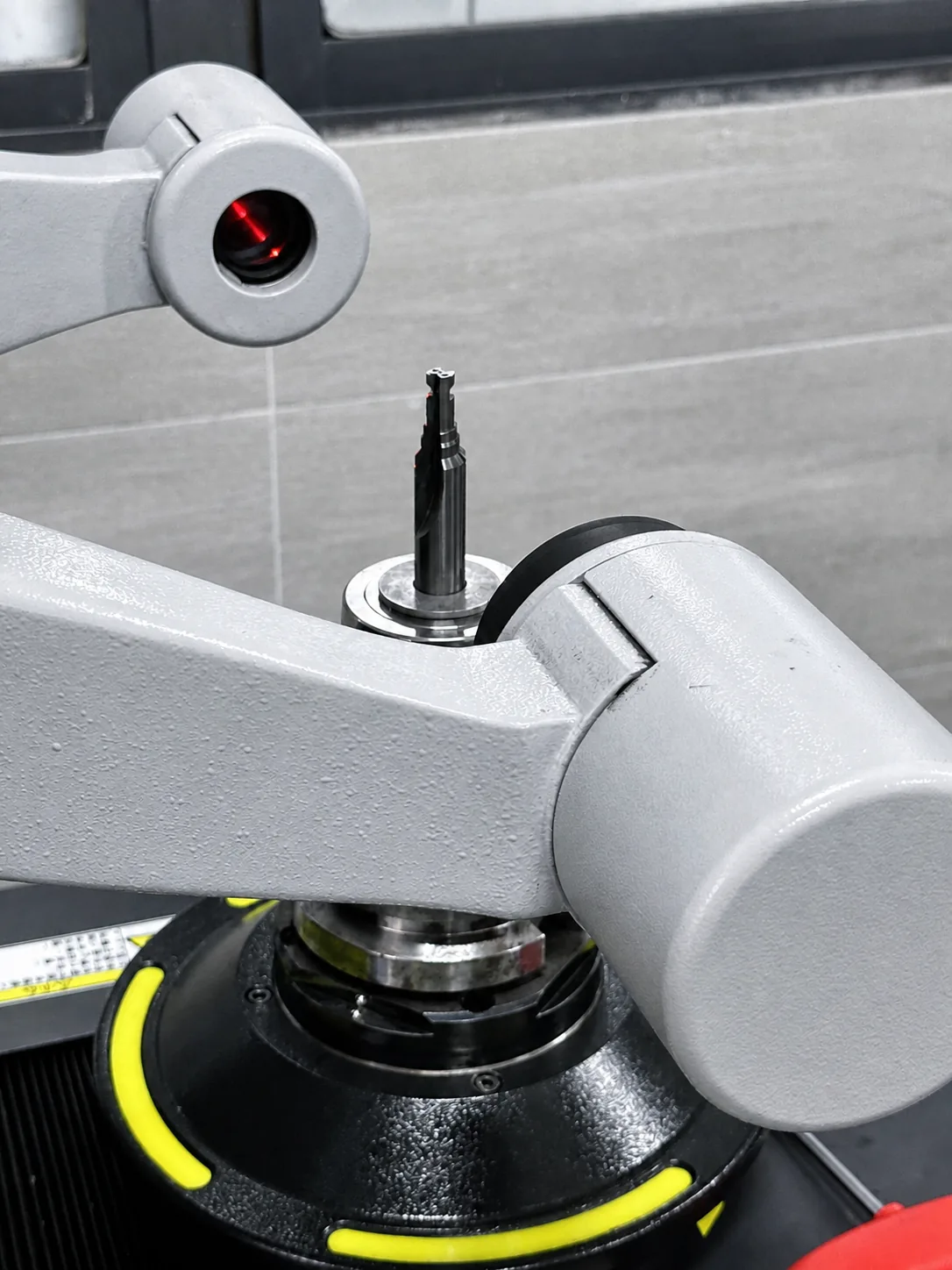
Repeating marks or a finish that changes from one hole to the next justify a runout and setup check. Inspect the holder, contact surfaces, seating, and reamer condition. Then use an indicator or presetter to check the assembled tool rather than relying on the condition of the reamer alone.
Minimize overhang and keep the toolholding and workholding secure. Those are not cosmetic setup details. They are part of the cutting system, and a loose or compliant setup can make a feed-and-speed change look effective on one hole and ineffective on the next.
Rubbing, torn material, or built-up edge: confirm that the reamer can cut
If the finish looks rubbed, torn, or smeared, go back to stock and cutting action. Inspect the cutting chamfers, margins, and general tool condition before assigning the defect to a program value. Unequal chamfers and incorrect margins are separate geometry issues in the manufacturer troubleshooting guidance.
Then inspect the chips and the cutting zone. In a deep hole, chip packing raises friction and can damage both finish and tool. Chip evacuation and coolant or lubricant delivery are part of the diagnosis because the local heat and adhesion behavior depend on the work material, tool geometry, hole type, and delivery method. The evidence supports this as a branch to inspect. It does not support one fluid or one flute style for every job.
Chatter: establish a usable starting point, then test one change
Chatter can have a parameter component, but it also depends on rigidity, alignment, and whether the tool is actually removing a stable amount of material. Do not start by changing several items at once. First verify stock, runout, overhang, and workholding. If those checks are sound, make one parameter change within the selected tool supplier’s guidance and compare the next hole.
Use vendor values as a starting relationship, not a recipe
Kennametal publishes the following rule-of-thumb stock allowances. They are useful as a documented starting reference, not as instructions for every job. Before using them, confirm the actual reamer family, work material, hole diameter, and whether the value is being interpreted as radial or diametral stock.
| Hole diameter band in Kennametal’s guide | Rule-of-thumb stock allowance |
|---|---|
| Below 1/4 in | 0.010 in |
| 1/4 to 1/2 in | 0.015 in |
| 1/2 to 1-1/2 in | 0.025 in |
The same guide gives a drilling-relative starting relationship for chatter control: feed at 200 to 300% of drilling feed and cutting speed at about two-thirds of drilling cutting speed, paired with minimal overhang and secure toolholding. This is not a machine-ready RPM or IPR recommendation. It is usable only after the drilling baseline, material, and tool family are known, and it still needs confirmation against the selected supplier’s data.
Do not force a single flute rule
Flute direction is an area where copying a short rule can create a bad decision. The available guidance contains a bounded conflict, and one captured extraction is malformed. For that reason, this article does not declare a right-hand or left-hand spiral correct in every case.
Use the selected tool supplier’s application guidance for the actual hole type, material, and tool family. The need to evacuate chips is real, but it does not turn a general chip-control principle into a fixed flute-selection rule.
Run one controlled verification hole
Use a repeatable sequence:
- Record the baseline: material, hole type and depth, prehole measurement, stock basis, reamer, holder, coolant delivery, and the visible finish.
- Correct the earliest failed branch. For example, correct a prehole or runout problem before adjusting a downstream parameter.
- Change one controlled variable for the next hole. Do not change stock, speed, feed, coolant, and tool geometry together.
- Compare finish and size, then repeat the result before treating the change as a cause.
This sequence takes longer than changing a setting at random, but it keeps a confounded trial from becoming a shop rule. A good reaming surface finish starts with a controlled prehole, a reamer that can cut the intended stock and a stable path through the operation.
Sources and scope
The diagnostic branches and vendor-scoped starting values in this article are based on Kennametal's reaming guide and Super Tool's reaming problem-solving table. This is an informational troubleshooting article. It does not recommend or make a performance claim for a specific SCT product.