Перейти к содержимому
Types of Tool Wear: How to Identify the Mechanism and Correct the Process
The useful way to handle types of tool wear is not to match a damaged edge to a generic cure. First state what is actually observed: the location of wear, transferred material, a crack pattern, or a chipped edge. Then ask what mechanism could create it, review the recent process history, and make one test that can confirm or reject that explanation. The same visible damage can arise from more than one mechanism, so a wear name is a starting question rather than a remedy.
This is a text-first diagnostic. No accepted local wear-photo set supports an image atlas, and neither a supplier checklist nor a single tool-life experiment can supply a universal correction. The goal is a more useful next action: connect the observation to conditions that can be checked on the actual process.
Start with location, then mechanism
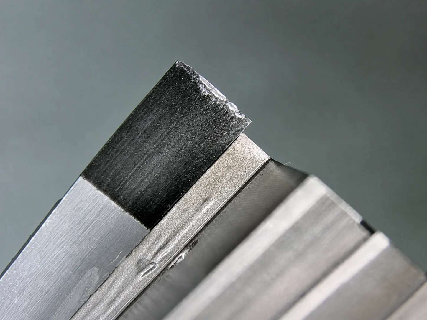
Flank wear is wear along the clearance face. It can be associated with abrasion or erosion at lower speed and with diffusion as thermal loading rises, but the mechanism still depends on the tool and work material, coating, speed, temperature, and chip contact. It is often a predictable end-of-life pattern when another failure does not intervene; that does not mean every worn flank has the same cause.
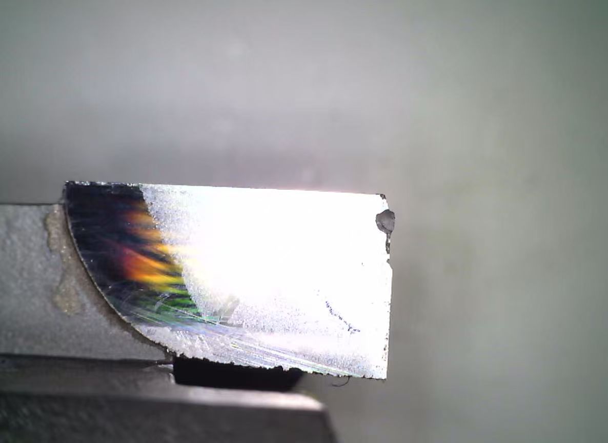
Crater wear develops at the hot tool-chip contact on the rake face. Diffusion, decomposition, abrasion, and adhesion can all participate, and a growing crater can weaken the cutting edge enough to contribute to chipping. Built-up edge is different again: it is adhered work material pressure-welded to the edge. When that material detaches, it can remove tool material and leave secondary chipping or flank damage. Confirm material transfer before treating it as built-up edge.
Use the pattern as a question, not a remedy
| Observation in words | Ask before changing the process | First validation focus |
|---|---|---|
| Flank wear on the clearance face | Is the change consistent with abrasion, erosion, or higher thermal load under this tool, material, coating, speed, and chip contact? | Compare the wear progression with the recent operating history; do not assume one cause from location alone. |
| Crater wear on the rake face | Is hot chip contact and the associated diffusion, decomposition, abrasion, or adhesion mechanism plausible? | Inspect the rake-face pattern and review the grade, material, thermal history, and chip contact. |
| Built-up edge or transferred material | Is work material actually adhering to and then detaching from the edge? | Confirm transfer before attributing the damage to another wear mode. |
| Чиппинг | Is the edge seeing mechanical instability, interrupted loading, hard inclusions, or a brittleness mismatch? | Check load interruptions, support, and whether the edge is suitable for the actual load. |
| Thermal cracking | Is cyclic temperature change involved, including intermittent coolant? | Review the thermal cycle and coolant behavior rather than treating every crack as a mechanical chip. |
The table does not promise a cure. It narrows the next question. Chipping and thermal cracking are particularly easy to conflate if the process history is missing: one points toward mechanical loading or edge brittleness, while the other points toward cyclic temperature gradients and can be aggravated by intermittent coolant.
Keep experiments attached to their conditions
Numbers can be useful when they preserve the experiment that produced them. In Tony Schmitz’s milling demonstration, a 19.1 mm single-insert uncoated-carbide end mill cut 1018 steel at 4.76 mm radial DOC, 3 mm axial DOC, and 0.06 mm/tooth, with a measured 0.3 mm flank-wear limit. The fitted model belongs to that cutter, material, machine, interval, engagement, and limit; it is not a default tool-life model.
The same boundary applies to a 2023 AISI 4140 crater-wear study. It compared named uncoated, TiN-coated, and laser-structured rake faces at 283 m/min, 0.1 mm/min feed as reported, and 0.1 mm DOC. Its reported crater depths belong to that named insert, material, coolant, repeated CNC-lathe experiment, and measurement method. Those values can explain why conditions matter; they do not supply a setting for another process.
Validate the process before generalizing
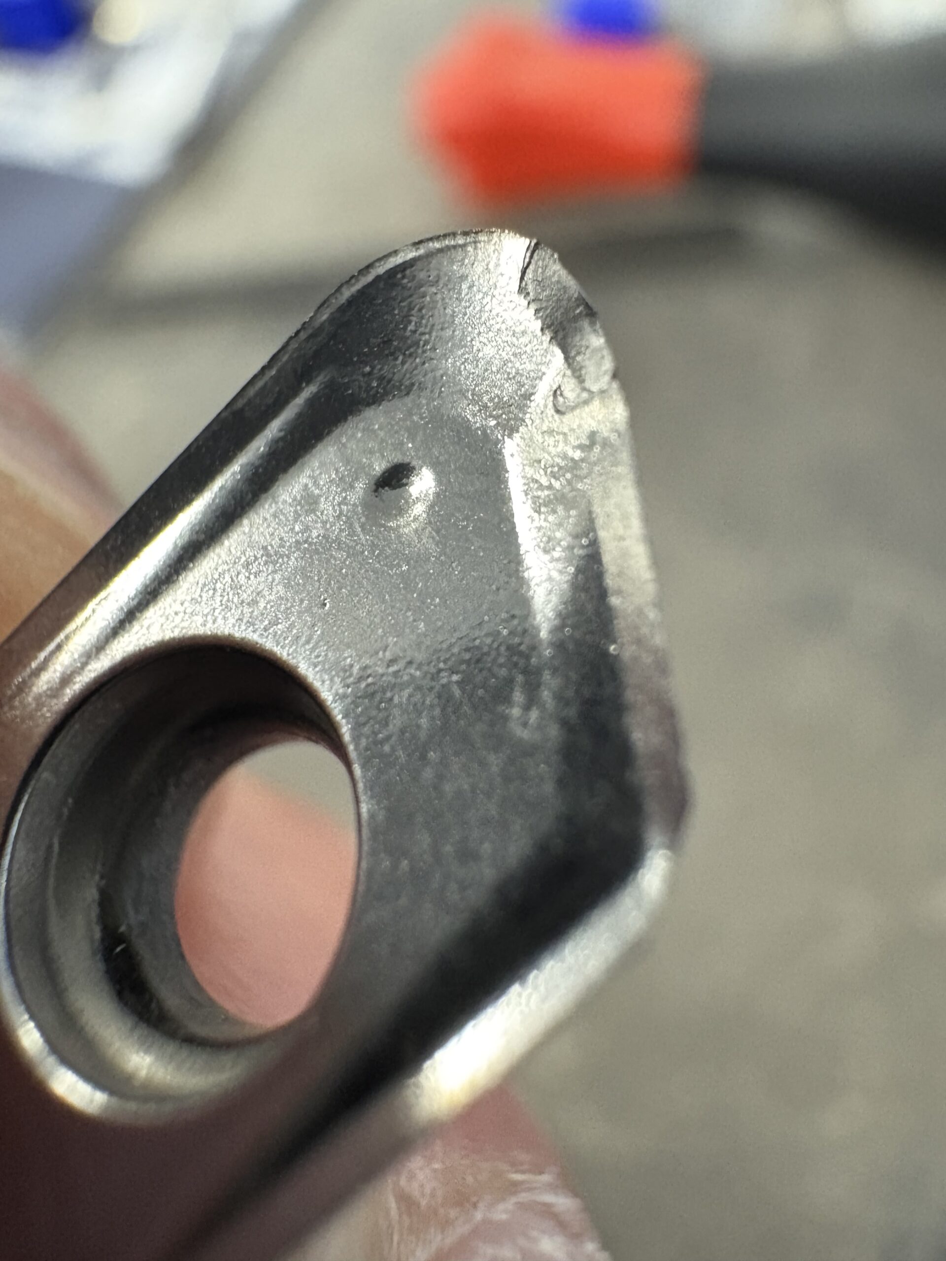
The accepted shop-floor cases reinforce the same discipline. Inconel 718 and prehardened-D2 discussions pointed to stickout, engagement, work hardening, machine capability, and grade selection as variables that can dominate wear or breakage. They are useful reminders to inspect the process context. Their conflicting numerical replies are not parameter evidence and should not be turned into a recipe.
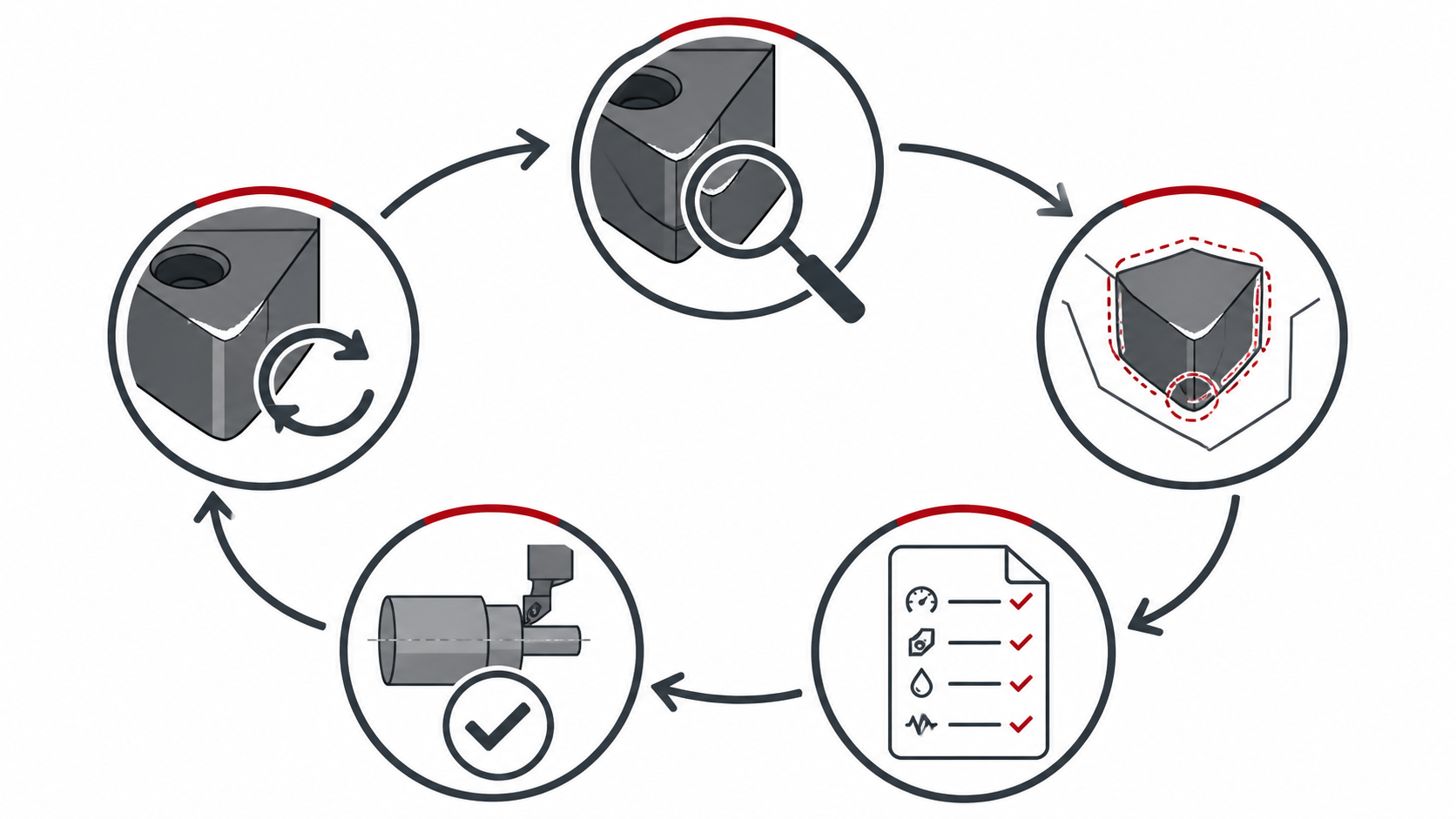
For a practical loop, record the observed location and progression, identify one plausible mechanism from the process history, change or inspect one variable that can test it, and then look at the edge again. If the result disagrees with the proposed mechanism, return to the observation and history instead of escalating a generic remedy.
Change the testable cause, then inspect again
Tool wear becomes actionable when it is tied to a specific cut. Use the pattern to choose the next check, then compare that explanation with the material, tool, coating, engagement, thermal cycle, machine support and process history. The next inspection should confirm or reject the proposed mechanism on the real process.