Ir al contenido
Cutting Speed Formula: Convert Surface Speed to RPM Without Mixing Units or Operations
En cutting speed formula converts a selected surface speed into spindle revolutions per minute. For metric inputs, use:
n = (Vc × 1000) / (π × D)
where n is RPM, Vc is cutting speed in metres per minute, and D is the active diameter in millimetres. For imperial inputs, use:
RPM = (SFM × 12) / (π × D)
where SFM is surface feet per minute and D is in inches.
Choose Vc or SFM from guidance for the actual material, tool and operation before using these equations. The result is an RPM to check against the machine and setup; feed is calculated separately.
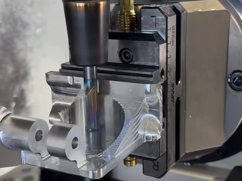
Use the exact relationship first
Cutting speed is linear velocity at the cutting interface. RPM is rotational speed. The relationship between surface speed and spindle speed follows the cutting circumference:
surface distance per minute = π × diameter × revolutions per minute
The metric equation includes 1000 because Vc is expressed in metres per minute while diameter is entered in millimetres. Rearranging the relationship gives the metric spindle speed formula:
n = (Vc × 1000) / (π × D)
The imperial equation includes 12 because SFM is expressed in feet per minute while diameter is entered in inches:
RPM = (SFM × 12) / (π × D)
Keep each unit system intact. A value in metres per minute cannot be placed into the imperial equation, and a diameter in inches cannot be placed into the metric equation without conversion. Writing the units beside the inputs is a simple way to catch that error before it reaches a program.
Why the shortcut constants differ
The familiar shop constants are rounded forms of the same equations:
1000 / π = 318.3099…, so metric RPM is sometimes written as(Vc × 318) / Dor, more loosely,(Vc × 320) / D.12 / π = 3.8197…, so the imperial SFM to RPM conversion is commonly written as(SFM × 3.82) / D. The still-looser constant 4 gives a higher result.
The distinction is small in some cases and meaningful in others. Using 320 instead of 1000/π makes the calculated metric RPM about 0.53% high. Using 4 instead of 12/π makes the imperial result about 4.72% high. That difference then carries into any feed rate calculated from RPM.
Keep the π-based equation in setup documentation and spreadsheets. Round the final result only to a command the machine can use. A rounded shortcut can be a quick check, but it should not hide the unit system or become an unexplained constant.
Choose the surface that is actually moving through the cut
Diameter is not a generic field. It represents the surface whose tangential speed is being converted.
Identify the rotating surface at the cut. Record whether D is the cutter diameter, workpiece diameter or a geometry-specific effective diameter so the calculation can be repeated correctly.
| Operación | Diameter used in the conversion | Feed model after RPM is chosen | Condition to check |
|---|---|---|---|
| Fresado | Rotating cutter outside diameter, or a toolmaker-defined effective diameter where geometry changes it | Feed per tooth × flutes × RPM | Partial radial engagement can invoke chip thinning |
| Brocas | Drill outside diameter for the basic circumference conversion | Feed per revolution × RPM | Use drill- and operation-specific feed guidance |
| Torneado | Workpiece diameter at the cutting location | Feed per revolution × RPM | Surface speed changes with diameter at fixed RPM |
For a conventional fresa de metal duro monobloque or drill, the basic calculation uses the rotating tool diameter. Some cutter geometries do not cut at their nominal outside diameter in every toolpath. In those cases, use the effective-diameter method supplied for that geometry rather than inventing a correction.
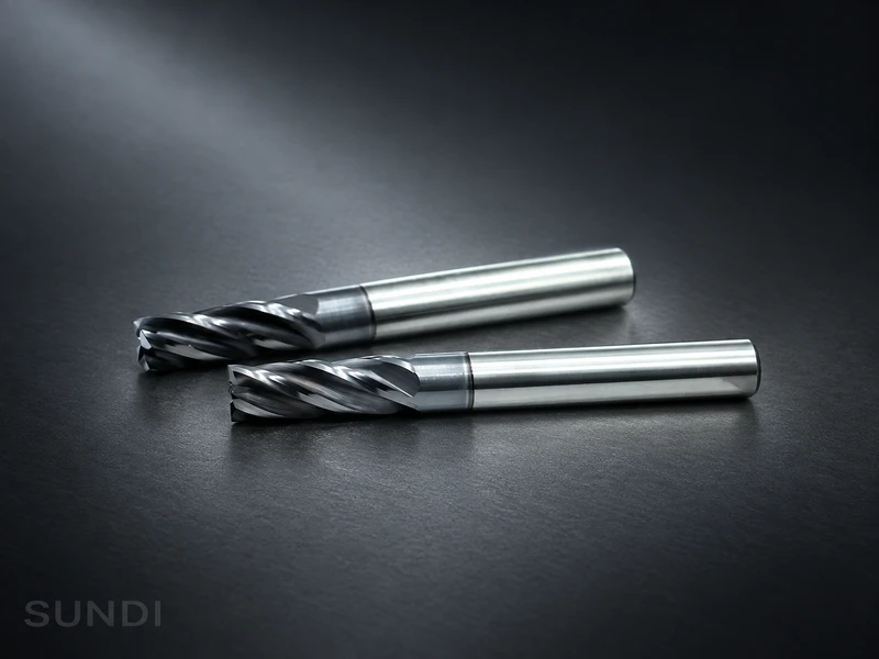
Cutting speed formula for turning and lathe work
In turning, use the workpiece diameter at the cutting location, not the insert size. The equations above are unchanged. If RPM stays fixed while the tool moves to a smaller workpiece diameter, surface speed falls.
A lathe’s constant-surface-speed control can change RPM as diameter changes, but it still needs a programmed RPM ceiling and secure workholding. Record the diameter used alongside the speed calculation.
RPM is not feed
The cutting speed formula ends at RPM. Feed requires another input and an operation-specific model.
For milling:
feed rate = RPM × number of flutes × feed per tooth
Feed per tooth is not produced by the speed equation. It comes from tool and application data conditioned by the material, cutter geometry, engagement, setup, and desired result.
For drilling and turning, feed is commonly programmed per revolution:
linear feed rate = RPM × feed per revolution
Do not move a milling feed-per-tooth value into a turning or drilling calculation merely because the RPM equation looks similar. The circumference relationship is shared; the feed model is not.
Milling also has a geometry limit. Below roughly half the cutter diameter in radial engagement, chip thinning can make programmed feed per tooth different from actual chip thickness. The simple milling feed equation still performs its arithmetic, but the feed-per-tooth input may need a geometry-specific correction. Use the cutter supplier’s chip-thinning or effective-diameter method for that toolpath.
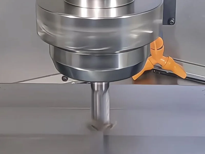
Worked examples: metric and imperial
The following numbers are assumed inputs chosen only to show the arithmetic. They are not cutting-speed recommendations for a material, tool, or operation.
Metric example: Vc to RPM
Assume:
Vc = 100 m/minD = 10 mm
Substitute the values without changing units:
n = (100 × 1000) / (π × 10) = 3,183.1 RPM
A practical command might be 3,180 RPM if the machine accepts that increment. At about 3,183 RPM, the 10 mm active diameter produces the assumed 100 m/min surface speed.
Imperial example: SFM to RPM
Assume:
SFM = 300 ft/minD = 0.500 in
Using the exact equation:
RPM = (300 × 12) / (π × 0.500) = 2,291.8 RPM
The rounded 3.82 check gives (300 × 3.82) / 0.500 = 2,292 RPM. The close agreement is expected because 3.82 is a rounded form of 12/π.
When the machine cannot run the calculated RPM
Suppose the metric example is assigned to a spindle limited to 2,500 RPM. Do not enter 3,183 RPM and assume the control will make every related value safe. Retain a permitted command, then calculate the surface speed the machine will actually produce:
Vc = (π × D × n) / 1000
Para D = 10 mm y n = 2,500 RPM:
Vc = (π × 10 × 2500) / 1000 = 78.5 m/min
Now evaluate 78.5 m/min against the conditioned tool/application data. Also check whether the spindle has suitable torque and power at 2,500 RPM; an RPM limit is not the only machine limit.
Feed must be recalculated from the RPM that will actually run. For example, if an application-specific milling input had already established four flutes and 0.05 mm/tooth, then:
feed rate = 2,500 × 4 × 0.05 = 500 mm/min
En 0.05 mm/tooth value is another assumed teaching input, not a recommendation. Its purpose is to show why feed cannot remain attached to the rejected 3,183 RPM value.
Blindly lowering feed can make the edge rub instead of form the intended chip, adding heat. Blindly retaining or increasing feed per tooth can overload the edge or crowd chip evacuation. If the cutting-speed input, chip-load input, machine limit, or geometry method is unknown, stop the calculation and obtain qualified application data before cutting.
Interactive calculation
Cutting speed to RPM calculator
Enter the cutting speed selected for your tool and material, then the active diameter. Add feed data or a spindle limit if available.
- Calculated spindle speed
- —
- RPM after optional limit
- —
- Surface speed at this RPM
- —
- Linear feed rate
- —
Enter cutting speed and diameter to calculate.
RPM = (Vc × 1000) / (π × D). Milling feed = RPM × flutes × feed per tooth.
Results are arithmetic outputs, not recommended cutting conditions. The RPM limit caps the calculation; it does not verify torque, power, workholding or tool suitability. Feed uses the unrounded RPM after the limit. Recalculate after rounding a machine command. Example values are for teaching only.Record a setting that can be checked and reused
Before the first cut, record the chain that produced the command:
- Work material: grade, hardness or condition where known, and stock state.
- Tool: identity, cutting material, diameter, flute count where applicable, and condition.
- Speed input: selected Vc or SFM, its source, and the conditions attached to it.
- Conversion: equation and unit system, calculated RPM, commanded RPM, and actual surface speed after any cap or rounding.
- Feed: feed per tooth or feed per revolution, its source, and the equation used to obtain linear feed.
- Configuración: radial and axial engagement, holder, measured runout where relevant, stickout, workholding, coolant delivery, and chip evacuation.
- Observation: spindle load, chip form and colour, sound, finish, wear, and any one controlled adjustment made after the first check.
For subsequent adjustments, change one variable at a time where the process permits and keep the observation with the setting.
A reusable setting is the recorded, observed result under those conditions—not the calculator output alone.