Saltar para o conteúdo
Router Bit Burning: Find the Cause from the Burn Pattern
Router bit burning means heat is building faster than the cut can form and remove chips. That heat may come from a low feed-to-RPM ratio, but it can also come from resin on the edge, a damaged bit, trapped chips, excess engagement, a slow corner, or a mechanical problem. Do not change every setting at once.
Check three things first. Stop the machine and inspect the bit and collet. Look at the waste and mark where the burn appears. Then verify the actual feed and RPM at that location, including any corner slowdown, plunge, or pause. Those observations decide which variable deserves the first test.
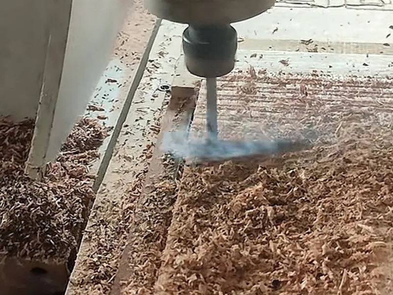
Read the burn pattern before changing settings
A burn mark is a routing clue, not a one-cause diagnosis. Use the pattern to choose the next check.
| O que observas | Leading diagnostic branch | Check next | First controlled action |
|---|---|---|---|
| A dark trail follows most of a straight cut and the waste is mostly fine dust | The edge may be rubbing because chip thickness is too low | Actual feed, actual RPM, participating cutting edges, and tool condition | Hold everything else constant and test either feed or RPM |
| A process that used to cut cleanly now burns and the edge carries pitch or resin | Buildup or edge wear may be raising friction and blocking the flute | Cleaned edge condition and a known-good tool comparison | Clean and inspect before changing parameters |
| The mark is darkest at inside corners, plunges, lead-ins, or pauses | Local dwell or controller deceleration may be adding contact time | Actual motion at the marked location | Remove an unnecessary pause or revise the entry/path motion |
| A blind slot or pocket burns more as it deepens | Chips may be trapped and recut | Chip path, extraction, flute direction, and pocket openness | Correct chip removal before changing several motion values |
| Burning begins where the tool meets heavy or irregular stock | Engagement may be overloading the cut or slowing real motion | Stock left, pass depth, radial engagement, sound, and machine load | Rough closer or split removal into suitable passes |
| Burning arrives with vibration, chatter, changing pitch, or inconsistent depth | Tool holding, runout, workholding, or tool damage may be involved | Bit, collet, nut, taper, workholding, and qualified runout check | Correct the mechanical condition before tuning parameters |
If several patterns occur together, check tool holding and workpiece security before running a parameter test.
Is the bit cutting chips or rubbing wood into dust?
If the burn follows most of the cut and the waste looks more like powder than chips, check chip thickness before slowing the machine. A cutting edge that advances too little per revolution can spend more time rubbing the same surface. That converts more of the cutting energy into heat. Router-table workshop guidance also identifies slow feed as a possible cause of burning.
Chip load describes the material removed by each participating cutting edge per revolution:
chip load = feed rate / (RPM x participating cutting edges)
The formula describes direction and does not supply a transferable setting. Raise feed while RPM and the bit stay fixed, and nominal chip load increases. Raise RPM while feed stays fixed, and nominal chip load decreases. A two-edge tool also divides the feed among more cutting events than a one-edge tool at the same feed and RPM. Start with application guidance for the actual bit, material and engagement, then check the machine and workholding limits.
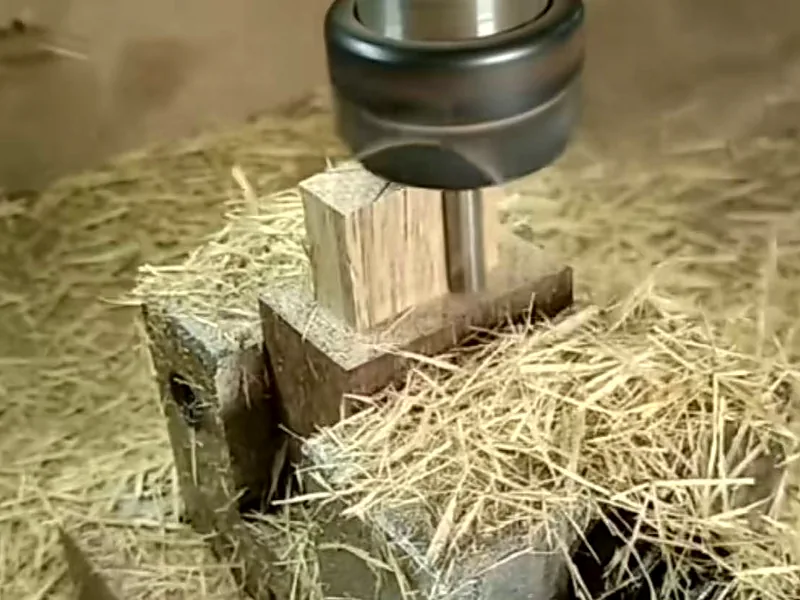
Test in the actual material with the setup recorded. Look for waste changing from powder toward formed chips, steadier sound and a cleaner edge without excessive machine load.
Change either feed or RPM first, not both, and keep the rest of the setup fixed so you can tell what helped.
More chip thickness is not automatically safer. Too much raises cutting force and can produce chatter, deflection, poor finish, lost position, or tool failure. A heavy industrial router and a light machine may reach those limits at very different points. The usable window belongs to the complete cutting system, not to the formula alone.
Did a previously clean process start burning?
When the same program, material, and setup used to cut cleanly, inspect the cutting edge before rewriting the process. Resin buildup and adhesive residue can coat the edge or narrow the flute. A dull or chipped edge needs more force to remove the same material. Both conditions increase friction and can degrade evacuation.
Stop the spindle, isolate the machine, and let the tool cool. Remove the bit according to the shop’s safe tool-change procedure. Under good light, look for resin film, rounded edges, chips, cracks, material packed in the flute, and contamination on the shank or collet. A change in sound, increasing cutting resistance, or worsening finish strengthens the case for an edge or holding problem, but none identifies the fault by itself.
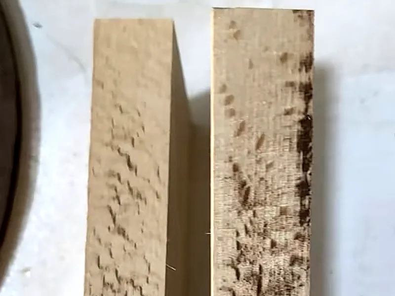
Clean with a product and brush that are compatible with the bit material, braze, guides, and coating. The goal is to reveal the edge, not polish or regrind it. Follow the tool’s maintenance instructions and keep routine cleaning separate from qualified sharpening or edge repair.
Repeat the baseline test only if the tool and holder are serviceable. If cleaning restores chip formation and finish, record the buildup as the corrected variable. If the cleaned edge remains damaged or cuts poorly, use a qualified sharpening service where the geometry permits it or replace the tool. Do not compensate for a damaged edge by pushing feed or RPM until the surface looks acceptable.
Are burn marks concentrated at corners, plunges, or pauses?
Burns that appear only at inside corners, small radii, plunges, lead-ins, or a programmed stop point indicate a local motion problem before they indicate a global feed problem. The programmed straight-line feed can look reasonable while the controller slows the tool sharply at one location. The edge then makes more contacts over less travel, increasing toolpath dwell and heat.
Map the burn onto the toolpath. Check the entry method, lead-in, plunge or ramp, corner radius, path junctions, minimum motion at the corner, and any deliberate pause. Listen for a pitch change at the same point. If the mark and slowdown repeat at the same coordinates, the location has more diagnostic value than the headline feed field.
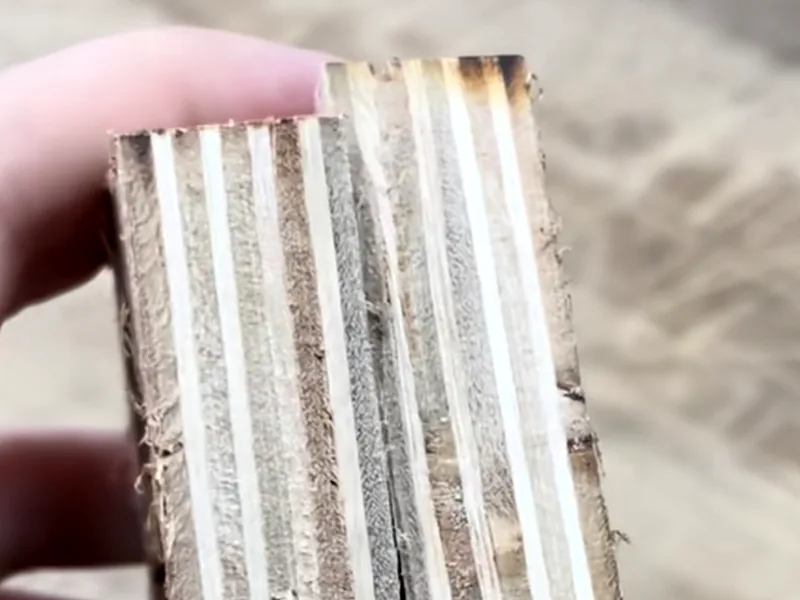
Change the local path first. Remove an unnecessary dwell, use an entry strategy the tool supports, or smooth a path transition, then repeat the same marked feature in scrap. Keep the bit, feed, RPM, engagement, extraction, and workholding fixed so the test still means something.
Check the revised motion against the controller, tool and workholding limits: reducing dwell must not create an abrupt or overloaded cut.
Does the cut burn more inside a slot or pocket?
If an open profile runs cleanly but a slot or pocket grows hotter or darker as it deepens, inspect chip evacuation. Nominal chip load can be plausible while chips remain in the channel. The bit then recuts hot waste instead of meeting fresh material, and packed chips reduce the space available for new chips to leave.
After a safe test pass, inspect where the chips actually went. Look inside the pocket, around the flute, and along the extraction route. Compare the amount and form of waste from the open cut with the enclosed cut. Check whether dust collection reaches the cutting zone and whether the flute pushes chips toward an exit or deeper into the work.
If extraction or airflow is inadequate, correct that path first and repeat the same pass. If the geometry sends chips in the wrong direction for the cut, then test a geometry or toolpath change that gives them a real exit.
Upcut, downcut, and compression geometries involve a tradeoff. The direction that clears a blind slot may not protect the required finish side or may change hold-down demand. Cut openness, material, depth, top and bottom surface requirements, and workholding decide the useful direction. “Better evacuation” is not permission to ignore those constraints.
Is excess stock or engagement loading the bit?
Burning at a heavy entry, an irregular lump of stock, or a wide contact zone points toward engagement. A finishing pass cannot finish cleanly if it is unexpectedly doing roughing work. High engagement can increase cutting force, slow the real path, pack the flute, and leave the edge rubbing when the machine cannot maintain the commanded motion.
Measure the stock that remains instead of relying on the intended roughing allowance. Check axial depth, radial engagement, cutting-edge length, stickout, spindle load, workholding, and the sound as the heavy region enters the cut. If only the high-stock region burns, changing a global RPM value may hide the path problem without fixing it.
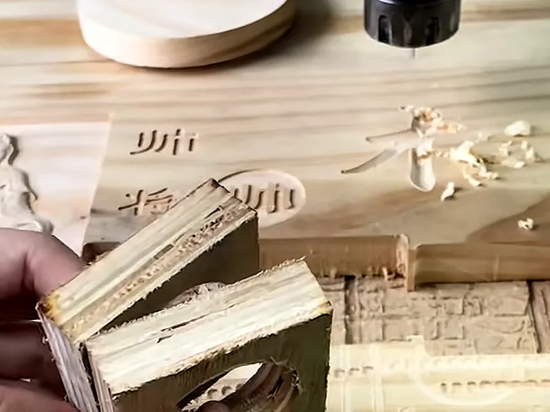
Rough closer to the line or divide removal into suitable passes. Leave a small, consistent finishing allowance so the final pass sees predictable engagement. Keep the finishing test otherwise unchanged.
Choose pass depth and allowance from the tool manufacturer’s guidance for the material and available machine capacity. A shallow pass can still rub when chip thickness is too low, so shallower is not automatically cooler.
When should you change geometry or flute direction?
Change geometry after the observations point to chip direction, finish-side control, or edge entry. A different cutter will not clean a dirty collet, repair a chipped edge, remove a programmed pause, or make irregular stock consistent.
Run labeled scrap tests when the burn changes with slot versus profile work, grain direction, surface side, or cutting direction. Hold the bit condition, feed, RPM, engagement, workholding, and path shape constant where possible. Compare chip exit, top and bottom finish, tearout, hold-down stability, sound, and heat marks.
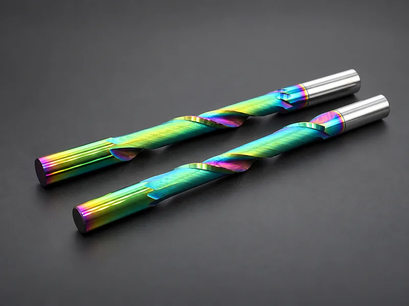
Upcut and downcut wood router tools differ in chip-flow tendencies, not a fixed quality ranking. Climb and conventional paths change how the edge enters the material, but wood structure, grain, machine motion control, workholding, and cut type can reverse the practical preference. A result from one board, router, or open edge is not a rule for a laminated panel or blind pocket.
Match geometry to the material, cut type, required finish side and chip path. Confirm dimensions and machine compatibility before fitting a replacement.
Do noise and uneven marks point to the mechanical setup?
New vibration, chatter, whining, rattling, inconsistent depth, or uneven marks around the cut are reasons to stop and inspect the setup. Runout, poor collet grip, debris in the taper, an imbalanced or damaged bit, part movement, or loose workholding can make the cutting edges participate unequally. One edge may carry most of the load while another rubs.
Do not tune through severe vibration. Stop the job and inspect the bit, collet, nut, taper, shank seating, spindle condition, and workholding. Use the shop’s qualified runout method and the machine or tool-holder specification. A known-good tool and holder can help isolate the variable when the comparison is safe and controlled.
Correct the mechanical condition before changing feed or RPM. Otherwise, a parameter change may reduce the symptom while leaving tool retention, accuracy, spindle, or part-security risk in place.
Sound is a trigger for inspection, not a diagnostic instrument by itself. Use the runout tolerance that applies to the machine, holder, tool, and required finish.
What does a dark router-bit body actually tell you?
A dark tool body without burn marks on the workpiece does not prove that the cutting edge failed from heat. Resin can bake onto the body, and steel can discolor differently from a carbide edge. Appearance can justify cleaning and inspection, but it cannot supply a temperature measurement.
Clean the body with a compatible method, then inspect the cutting edge, flute, braze or coating, shank, and cutting performance. Compare the condition before and after cleaning. If the workpiece remains clean, the edge is undamaged, and performance is stable, the dark body was not enough evidence to rewrite the process.
If the edge is chipped, cracked, rounded, or still cuts poorly after cleaning, remove it from service for qualified evaluation. Do not declare the tool safe from a photograph, and do not infer a temperature from a color chart. The relevant evidence is the complete tool condition and cutting result.
Troubleshoot one variable at a time
Preserve the baseline before making a correction. Record the material and sheet condition, bit identity, flute count, geometry, stickout, tool age or use history, actual feed, actual RPM, depth, radial engagement, path, workholding, extraction, burn location, chip form, sound, and surface result.
- Make the tool and workpiece safe; clean and inspect the bit and collet.
- Match the burn location and waste to the table above, then verify actual motion at that location.
- Correct the identified chip-path, stock or mechanical problem before compensating with feed or RPM.
- Test one change on labeled scrap and compare chips, sound, load, finish and burn pattern with the baseline.
Stop the test if load rises abnormally, sound or vibration becomes severe, the tool or holder shows damage, the part moves, or the comparison cannot be made safely. Return to the last serviceable baseline. The goal is not to find the highest possible feed or lowest possible RPM. It is to identify the mechanism and document a stable cut for this bit, material, path, and machine.