Saltar para o conteúdo
Side Milling with an End Mill: Setup, Engagement, and Proof
Side milling with an end mill uses the cutter’s peripheral flutes to generate a wall, shoulder or side surface. One side of the cutter is engaged; the tool is not buried across its full diameter as it would be in a slot. That distinction changes the force path, chip thickness, deflection risk and inspection plan.
A dependable operation starts before any cutting values are entered. Define the wall and remaining stock, support the part against the expected radial force, keep the cutter assembly short, obtain data for the exact tool and work material, and plan radial engagement separately from axial engagement. Then simulate, make a proof cut, measure the wall at several locations and change only the cause that fits the evidence.
The aim is not merely to produce one acceptable pass. It is to establish a setup and process window that another operator can identify, verify and repeat.
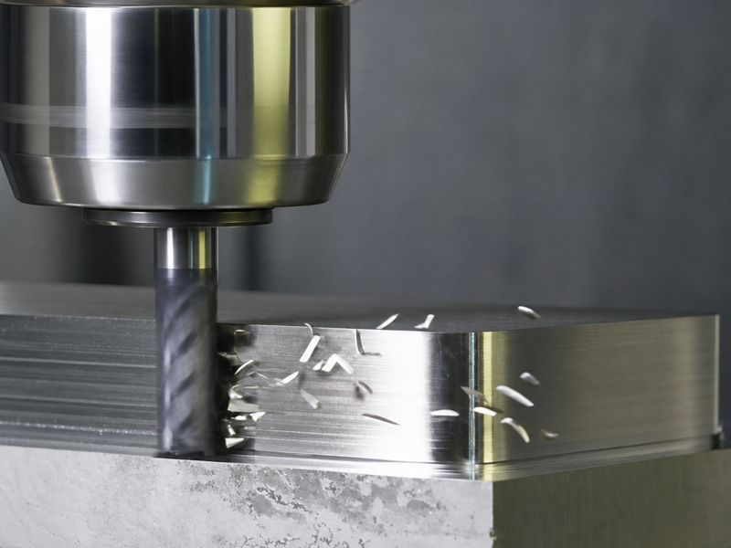
Define the wall, stock and inspection before selecting a tool
Start with the finished feature. Identify the wall’s controlling datum, length, height, size tolerance, straightness, squareness, surface requirement and any blend or corner condition. Decide whether the end mill must create the full wall in one axial band or whether the feature can be divided into levels. Also identify the surfaces that will be used to inspect it.
Map the stock around that feature. A side-milling path should have a known amount of material on the engaged side and a clear exit for chips. Cast skin, scale, interrupted stock or an uneven rough face can cause load changes that a nominal width-of-cut value does not describe. If the stock condition is uncertain, establish it with a separate roughing operation or inspection before planning a close-tolerance finish pass.
Keep the operation distinct from adjacent processes:
- In side milling, the peripheral edge generates the wall while one side of the cutter is engaged.
- In full-width slotting, material surrounds both sides of the cutter and chip escape is more restricted.
- In face milling with an end mill, the end cutting edges primarily generate a surface normal to the spindle axis.
Search logs sometimes reduce the operation to the phrase side milling with end mill. The missing article does not change the process: the peripheral edge generates the wall, and only one side of the cutter should be treated as radially engaged.
An end mill can contact with both its end and periphery near a shoulder, but the wall-generating mechanism remains peripheral cutting. That is why radial force, cutter bending and wall taper deserve specific attention here.
Define inspection before programming. For a tall wall, one measurement near the top cannot reveal whether the surface changes with height. For a long wall, one measurement at the center cannot separate a uniform size offset from travel-related error. Plan to check size near the top and bottom of the cut and at more than one position along the toolpath. Add squareness to the datum surface, wall straightness and finish observations as the drawing requires.
Stop before tool selection if the datum is ambiguous, the wall cannot be reached without a collision, the remaining stock is unknown, or the intended inspection method cannot resolve the tolerance. Cutting first does not make those uncertainties easier to diagnose.
Build a short, rigid force path
The cutting force must travel through the workpiece, fixture, table, machine structure, spindle, holder and tool. Side milling puts a radial load into that chain. Any flexible or poorly seated element can move the wall even when the programmed path is correct.
Clean and inspect the locating surfaces. A chip under the workpiece, a burr on a parallel or an uneven clamp load can tilt the part. Verify that the work is seated after final tightening; do not assume it remained seated because it was correct before clamping. Place support close enough to the cutting zone that the wall is not acting as a spring. Thin sections may require backing, staged stock removal or a finish pass after stresses have redistributed.
Consider the direction in which the cut will push the work. The fixture should resist that force through solid locators rather than depend mainly on friction. On a manual machine, table locks, gib condition and backlash affect how the system reacts. On a CNC machine, axis condition, servo response and compensation state still belong to the setup evidence; control does not remove mechanical compliance.
Check the spindle and holder connection. Inspect taper and contact surfaces, holder condition and clamping method. Measure runout at a meaningful location near the cutting tool rather than relying only on a clean-looking holder. Excessive runout can make one flute carry more load, create a repeating surface pattern and accelerate local wear.
Machine geometry matters when a wall is supposed to be square. A spindle or axis alignment error can produce a repeatable angular result. Cutter deflection can also create wall taper, but changing feed cannot correct a tilted workpiece, poor tram or axis error. Establish the mechanical baseline before using the cut as a machine-geometry test.
Stop if the work moves under a safe verification load, the toolholder is damaged, runout is outside the tool or process requirement, a clamp enters the clearance envelope, or the machine condition cannot be verified. These are setup failures, not parameter-tuning opportunities.
Select the cutter and holder as one assembly
Choose the tool from the wall geometry outward. The cutting length must cover the intended axial engagement without rubbing an unrelieved shank or transition. At the same time, total reach and tool stickout should be no longer than necessary. A cutter that technically reaches the wall but projects far beyond the holder can deflect enough to change size and finish.
Diameter affects access, stiffness, chip space and the programmed path. Flute count and flute form affect chip capacity and the feed calculation. Edge preparation, substrate, coating and geometry must match the material and operation according to the toolmaker’s model-level data. Do not infer that every tool in a family has identical cutting recommendations.
Treat the holder, gauge length and cutter as one qualified assembly. Record the item number, diameter, usable cutting length, flute count, holder, gauge length and measured runout. If the cutter is reground, confirm its actual diameter and approved application data; the original catalog diameter may no longer describe the programmed compensation.
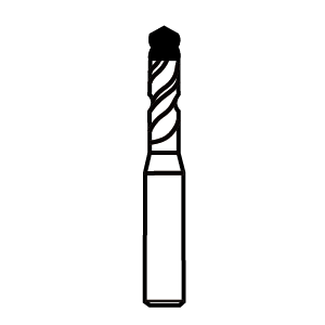
To identify candidate families, use the fresa de topo de metal duro as a navigation point. It does not replace the exact cutter drawing, cutting-data source or application confirmation. A collection-page label alone is not evidence that a particular geometry, coating or cutting condition is suitable.
Also inspect access along the complete path. The flute may clear while the holder, collet nut or reduced-neck transition collides with a shoulder. Model the assembled gauge length and holder envelope, not just the nominal cutting diameter.
Plan radial and axial engagement separately
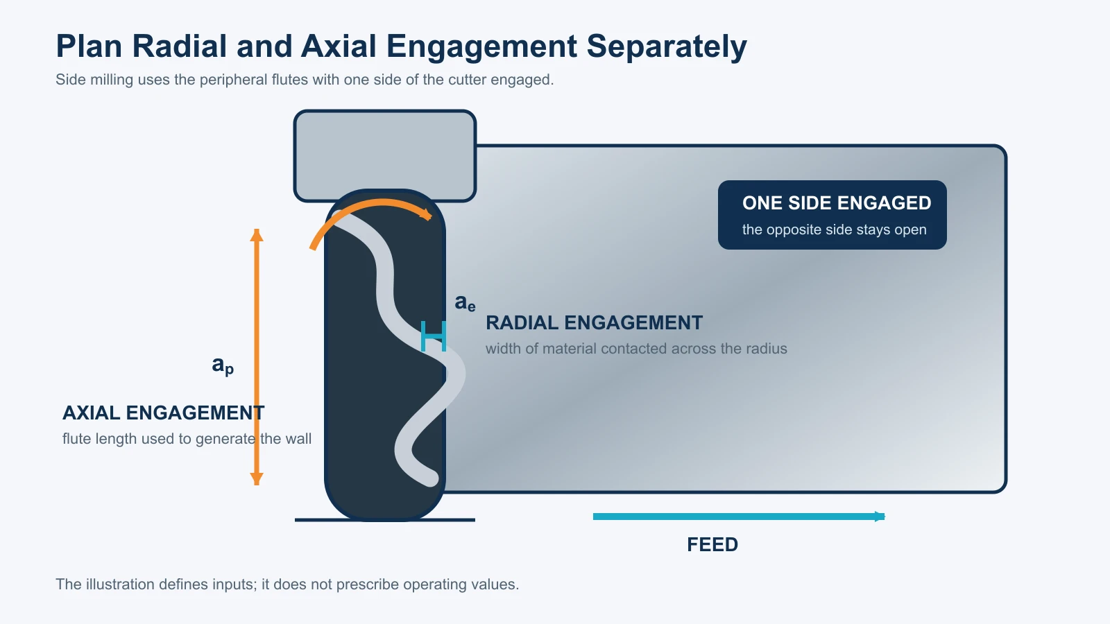
Radial engagement is the width of material contacted across the cutter radius. Axial engagement is the length of the peripheral edge participating along the cutter axis. They affect the operation differently and should appear as separate inputs in the setup record.
Increasing radial engagement changes the engaged arc, chip formation, force and chip-exit condition. A light radial cut can produce chip thinning, but any adjustment should follow the exact toolmaker’s method and applicability limits. It is unsafe to apply a generic multiplier without knowing cutter geometry, programmed feed basis and engagement definition.
Axial engagement determines how much of the flute band is used to generate the wall. If the same narrow band repeatedly contacts the work, wear can concentrate there while unused flute length remains sharp. A later pass that shifts the contact band can then encounter a worn-to-sharp transition. This does not mean that maximum axial engagement is always more efficient; it means the used flute band, reach, stiffness, chip evacuation and toolmaker limits must be considered together.
Separate roughing from finishing when the feature and stock justify it. Roughing can leave a controlled radial allowance so the finish pass encounters a more uniform wall. The finish pass should remove enough material to cut consistently rather than merely rub high spots, but its value must come from the qualified process, not from a universal minimum.
For a tall wall, decide whether one full-height pass is stable or whether staged axial levels are required. If levels are used, plan overlap and blending so they do not create a step or visible seam. If the final wall is generated in one pass, verify that cutting length, chip evacuation and deflection remain acceptable over the full axial engagement.
Document both engagements for every proof cut. Writing only “depth of cut” is ambiguous and makes later diagnosis difficult.
Choose direction, entry and exit deliberately
Climb milling and conventional milling reverse the relationship between cutter rotation and feed at the engaged side. The choice changes how chip thickness develops and how force is directed into the machine and fixture. It should not be reduced to “always use climb milling.”
On a rigid CNC setup with controlled backlash, climb milling is often considered for wall finishing, but cutter requirements, workholding and machine condition still control the decision. On a manual machine with meaningful backlash, a climb cut can pull the table into the cutter. Conventional milling may be required, or the setup may need a different strategy. Surface scale, work hardening, part flexibility and force direction can also influence the choice.
Plan the approach so the cutter does not strike the wall at full engagement. Use an entry method that builds load predictably and is compatible with the control, tool and stock. Avoid dwelling against the finished wall; a stationary rotating cutter can rub, mark the surface or unload and spring back differently. At exit, make sure the tool does not leave a thin unsupported corner in a way that breaks it away or raises a burr beyond the inspection plan.
Keep chips out of the cut. Recutting can damage finish and edges even when calculated feed is correct. Air, coolant or another approved evacuation method must suit the material, machine enclosure and qualified process. Do not create an operator exposure or scatter sharp chips to solve a chip-control problem.
For offset or compensation moves, confirm which side of the programmed contour the cutter occupies. A correct numerical offset entered on the wrong path side can remove the wall. Lead-in, lead-out and compensation activation should occur where enough stock and clearance exist for the control to execute them predictably.
Calculate commands from the selected tool data
Begin with the cutting-speed and feed-per-tooth data for the exact cutter, work material, material condition and side-milling engagement. Preserve the source and revision in the process record. If the source does not cover the actual reach, interruption, coolant condition or engagement, ask the toolmaker or qualify a conservative starting condition under controlled supervision.
For inch units, calculate spindle speed as:
RPM = (SFM × 3,82) ÷ diâmetro da lâmina em polegadas
Para unidades métricas:
RPM = (1000 × velocidade de corte em m/min) ÷ (π × diâmetro da fresa em mm)
Then calculate table feed:
Avanço da mesa = RPM × número real de ranhuras × avanço por dente
Use the actual diameter and actual flute count. Check the result against the machine’s usable spindle speed, feed, power and torque range. If the commanded RPM must be reduced to fit the machine, recalculate table feed from the achievable RPM; leaving feed unchanged changes feed per tooth.
These calculations create a command, not a guarantee. Tool stickout, radial engagement, axial engagement, runout, fixture stiffness and chip evacuation determine whether the command is suitable in this assembly. Any radial chip-thinning correction must come from an approved model or calculator whose input definitions match the operation.
Set an initial load-monitoring and inspection window. The operator needs to know which signals are expected, which require a controlled stop and which prohibit restart. Escalating spindle load, unstable sound, chip packing, visible tool damage, part movement or a collision risk are stop conditions. Do not finish the pass and inspect later.
Simulate and make one proof cut
Verify the toolpath with the real tool assembly and stock model. Check the wall side, cutter compensation, radial allowance, axial limits, holder clearance, approach, exit, retracts and clamp positions. Confirm that an optional stop or dry-run method does not itself create an unsafe path or an invalid feed condition.
Before contacting the part, confirm the work offset and tool length using the shop’s controlled method. A visual air cut can reveal gross side or clearance errors, but it does not prove the accuracy of an offset. Use independent verification appropriate to the machine and risk.
The first material cut should be a proof, not an unattended production run. If practical, choose a feature or allowance that permits measurement without sacrificing the part. Observe load trend, sound, chip evacuation and any visible movement. Stop immediately for a load spike, worsening vibration, chip blockage, cutter damage, holder contact or loss of workholding confidence.
After the proof cut, preserve evidence. Note the actual RPM and feed, both engagements, path direction, tool-compensation value, gauge length, runout, coolant or air condition and observed load. Inspect the cutting edges around the full circumference and along the axial contact band. One damaged flute points toward runout, local damage or unequal loading; a worn band at one height tells a different story from uniform edge wear.
Do not move directly into production because the wall looks smooth. A deflected cutter can leave a visually acceptable wall that is tapered or out of size.
Measure the whole wall, not one point
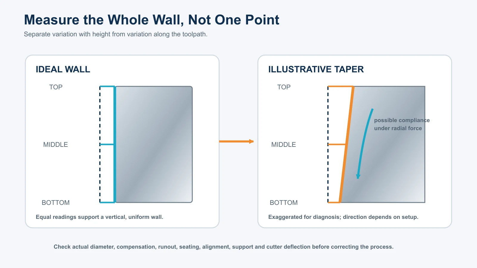
Measure according to the drawing and the planned inspection method. At minimum, distinguish variation with height from variation along travel.
Check wall size near the top and bottom of the engaged height. A systematic difference can indicate cutter bending, workpiece movement, spindle/axis alignment, local support or a change in the cutter’s effective contact. Then check at the beginning, middle and end of the path where the feature length and tolerance warrant it. A change along travel can indicate axis geometry, fixture seating, thermal effects, stock variation or tool wear during the pass.
Check squareness to the controlling datum rather than to a convenient but unrelated surface. Check straightness with a method that can resolve the specified tolerance. Record finish observations spatially: a repeating flute pattern, chatter marks, a rub mark at exit and a burr at one corner should not be collapsed into “poor finish.”
Relate the wall to process evidence:
- A uniform size offset with little shape change may point to compensation, actual diameter or offset setup.
- A wall that changes with height may point to tool deflection, spindle/axis alignment, workpiece tilt or support.
- A wall that changes along travel may point to seating, axis geometry, stock distribution, thermal drift or wear.
- A repeating pattern at flute spacing may point to runout, edge damage or unequal tooth loading.
- Wavy marks with changing load or sound may indicate chatter or a force-path weakness.
- Localized burrs or smearing may involve edge condition, material behavior, direction, exit or rubbing.
These are diagnostic branches, not automatic verdicts. Confirm each suspected cause with an independent check before changing the process.
Correct the cause that matches the wall evidence
Change one variable at a time and preserve the before-and-after measurement. If a uniform offset is the only error, verify actual tool diameter, compensation sign and offset value before changing cutting speed or feed. A parameter change is not a reliable way to correct a clerical offset.
For wall taper, first establish its direction and repeatability. Indicate the part and fixture seating, verify the datum, check spindle and axis geometry with an approved method, measure runout and inspect the tool assembly. Then evaluate cutter deflection: compare the taper response to gauge length, radial engagement, axial engagement, tool diameter, part support and direction of force. A taper that remains through major cutting-condition changes may be mechanical; a taper that responds consistently to force reduction may involve compliance. Either conclusion requires measurement.
For chatter, inspect the complete force path before randomly changing commands. Look for excessive tool stickout, unsupported wall height, loose or distant clamping, holder/runout problems, unstable engagement at entry, recutting chips and a worn edge. If the setup is sound, adjust only within toolmaker and machine limits and verify that both geometry and edge condition improve.
For poor finish without chatter, identify whether the marks repeat by flute, occur only at entry or exit, or follow the whole wall. Inspect every edge, chip evacuation and compensation moves. Do not polish away evidence before documenting it if the surface is needed for diagnosis.
For concentrated flute-band wear, verify the axial contact range and whether repeated passes reuse the same region. Review cutting length, staged levels and process sequence. Moving the contact band without understanding the worn-to-sharp transition can change cutting force abruptly.
After any correction, repeat the proof and the same spatial inspection. A change is not validated merely because sound improved; the wall, load, chips and tool edge must all remain acceptable.
Release the side-milling operation
Release the process only after the proof cut meets the dimensional, geometric, surface and tool-condition requirements. Record enough detail to reconstruct the qualified condition: machine, workholding and locator state; cutter and holder identifiers; actual diameter, flute count, cutting length, gauge length and runout; tool-data source and revision; RPM and table feed; radial and axial engagement; direction, entry, exit and compensation method; evacuation; inspection locations; and the accepted result window.
Define requalification triggers. A new cutter family, regrind, holder, gauge length, fixture, work material or heat-treatment condition can change the result. So can a machine crash, spindle service, axis adjustment, revised engagement or altered wall height. The released record should say which changes require a new proof cut rather than leaving that decision to memory.
Also define the production checks that protect the release: when to inspect wall size and taper, what load or sound change calls for a stop, how edge wear is reviewed and who can approve an offset correction. The useful endpoint of side milling is not a generic feeds-and-speeds number. It is a traceable operation in which setup, engagement, command, wall evidence and correction logic agree.