Ir al contenido
Why a Reamer Cuts Oversize: Diagnose One Variable at a Time
When a reamer cutting oversize leaves a bore outside tolerance, resist the urge to lower the speed, change the feed, and replace the tool in the same attempt. An oversize result can begin with the measurement, the pre-hole, the assembled tool, or the cut itself. Changing several inputs at once may produce a good hole, but it will not identify which condition failed—or whether the next part will fail again.
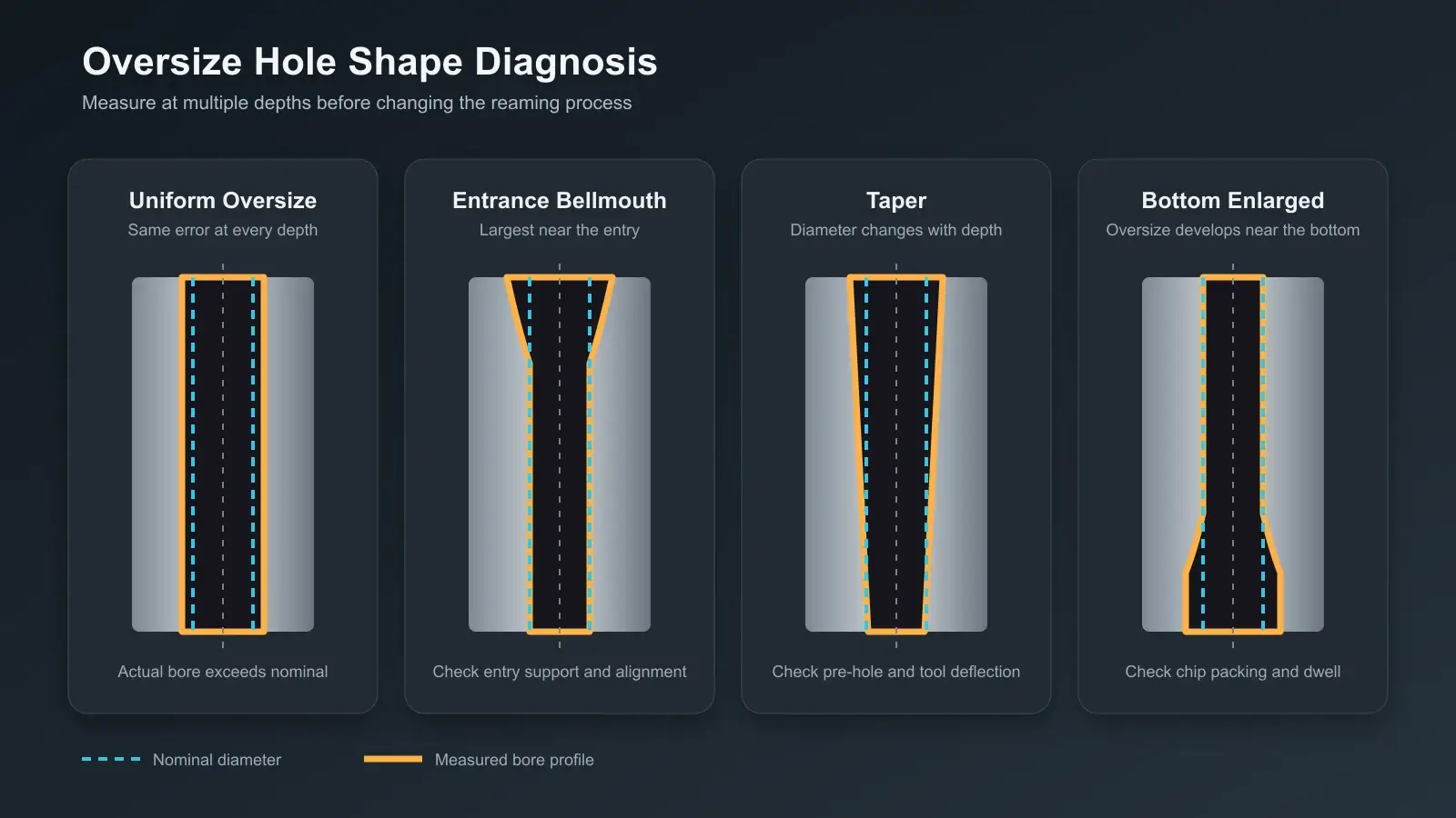
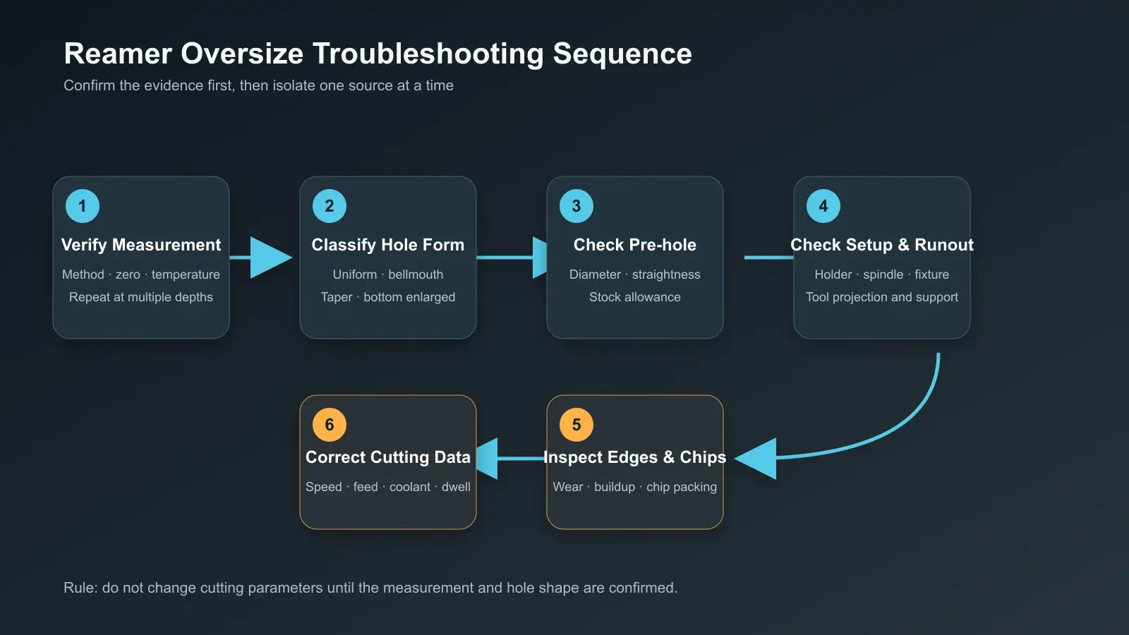
Start by confirming the error and mapping its shape. A bore that is uniformly oversize suggests a different path from an entry bellmouth, a taper, or a lower section that opens up. Preserve the failed setup, measure the hole at several depths and orientations, and let that pattern choose the next check. Correct one verified condition, then repeat the same measurement method.
Freeze the process before making another hole
The failed bore contains evidence. Preserve it before an operator cleans the holder, changes an offset, replaces the reamer, tops up coolant, or edits the program. Record the part and material lot, machine, spindle state, holder, tool identification, measured tool size, stickout, offset, cutting data, pre-hole operation, coolant or lubricant condition, and inspection method.
Keep the removed reamer and holder together until the assembled setup has been checked. Photograph the lead, flutes, and chips if their condition may change during cleaning. Save the program revision and note whether the failure appeared on the first part, developed after several parts, or followed a material, tool, holder, or coolant change.
This freeze is not paperwork for its own sake. It separates persistent causes from transient ones. If a holder is cleaned and the error disappears, contamination or seating becomes a strong hypothesis. If the tool, cutting data, gage, and coolant all change together, the shop has only a new process—not a diagnosis.
Prove that the hole is actually oversize
Before diagnosing the cut, verify the measurement system. Clean the bore and gage. Confirm that the instrument or master is suitable for the tolerance and has a current calibration status. Allow the part and gage to reach a controlled, comparable temperature when thermal growth is significant. Repeat the reading with the same contact method rather than mixing a two-point bore gage, air gage, plug, and coordinate measurement result as if they were interchangeable.
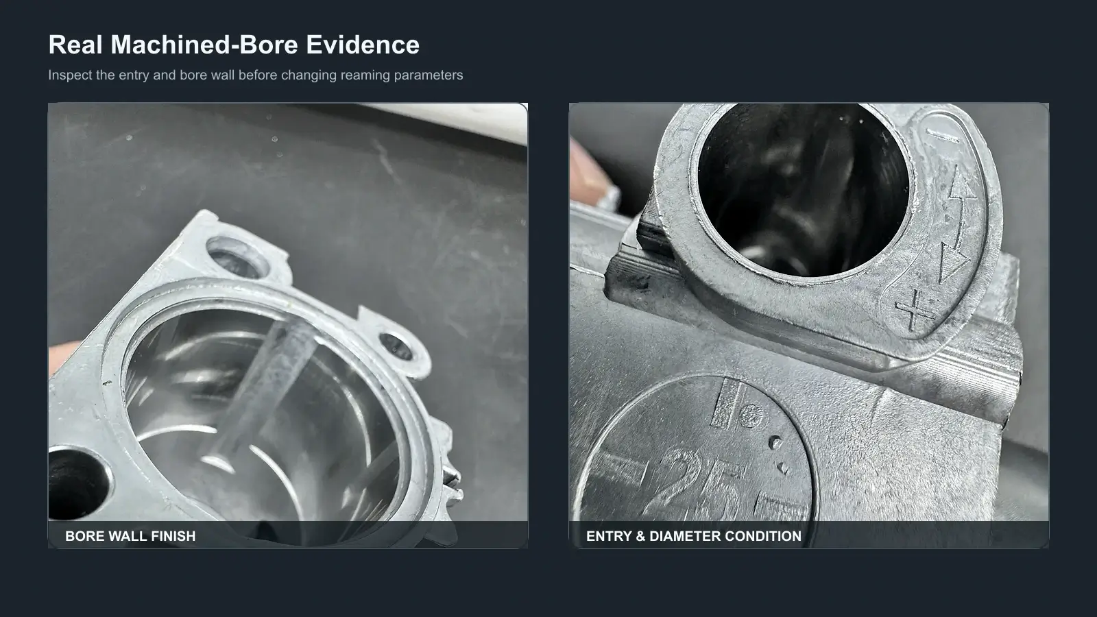
Measure at the entry, middle, and exit or bottom. At each depth, check more than one angular orientation when the method allows it. Record actual readings instead of writing only “oversize.” This distinguishes diameter shift from lobing, taper, bellmouth, local damage, or a measurement-access problem.
If repeated measurements do not agree, correct the gaging problem first and remap the bore. If they agree, keep the map as the baseline for every correction trial. A process change is not confirmed unless the same method shows the expected response.
Let the bore shape choose the next check
A reamer cuts oversize for several possible reasons, but their probability changes with the geometry of the error. Use the symptom as a routing signal rather than treating every cause equally.
The whole bore is uniformly oversize
A consistent diameter from entry to exit points first toward a systematic offset. Verify the gage against a known standard, measure the reamer where the manufacturer specifies, and compare the result with the required finished size. Then indicate the complete spindle-holder-reamer assembly close to the cutting lead. Clean and reseat the interfaces, repeat the indication, and document whether the runout changed.
If the gage check reveals bias, correct the inspection method and remap the original bore. If reseating changes assembled runout, correct the dirty, damaged, or mismatched interface and make one confirmation hole. If measurement and setup remain stable, inspect all lead edges for a consistent built-up edge, wear land, chipping, or incorrect tool condition. Only after those checks should an offset or cutting-condition change enter the trial.
The entry is larger than the rest
An enlarged entrance directs attention to approach alignment and initial lead engagement. Inspect the entry chamfer for concentricity and damage. Review the approach move, spindle start, feed engagement, and any dwell. Check whether the workholding, machine alignment, or holder causes the tool to enter off-axis and settle after it is guided by the bore.
If the bellmouth follows an uneven chamfer or displaced pre-hole, correct the entry preparation and retest. If witness marks begin at the mouth while the pre-hole is sound, remove an unnecessary dwell or correct the approach as the single trial change. If neither is present, return to assembled runout and lead-edge inspection rather than compensating the final diameter.
The bore changes size with depth
A taper or a lower section that opens up requires a depth-matched investigation. Measure the pre-hole at the same depths and orientations used for the finished bore. If its drift, taper, or local enlargement mirrors the reamed result, correct the drilling or boring process first. Reaming is principally a sizing and finishing operation; it generally follows the prepared hole and should not be expected to repair a major location or straightness error. Cutting Tool Engineering’s discussion of preparing a hole for reaming emphasizes both limited stock removal and the importance of the hole presented to the reamer.
If the pre-hole is stable, indicate the assembled reamer and inspect for a bent shank, damaged lead, unequal edge condition, or inadequate guidance. If those checks pass, look for a cause that accumulates with depth: packed or recut chips, blocked flutes, declining lubrication access, rubbing, or thermal growth.
A reviewed machinist discussion describes a bore that held size through much of its depth and then opened up near the lower section. The useful lesson from that depth-dependent reaming case is the diagnostic branching—check the pre-hole, runout, tool condition, chips, and heat—not the case’s dimensions or settings. Those values belong to that machine, tool, material, and inspection context.
Change the first condition that fails inspection, then repeat the identical depth map. If the lower section remains oversize, the result redirects the next check; it does not justify changing every remaining variable.
Size changes from part to part
Variation over a production run suggests a condition that changes with time. Plot bore size against part count. Add tool-edge appearance, material lot, coolant state, spindle or part temperature, holder cleaning, and gage verification to the record. Look for a change point rather than an average.
If diameter moves with edge buildup or wear, clean, recondition, adjust where the specific tool design permits, or replace the tool as one controlled intervention. If the shift coincides with a material lot or coolant change, restore or qualify that condition before editing cutting data. If the process record is stable but repeat gaging is not, fix measurement control before touching the machine.
Confirm the hypothesis with consecutive test features. One acceptable hole after an uncontrolled reset does not establish repeatability.
Inspect what the reamer inherited from the pre-hole
Measure the pre-hole before reaming, not only after the final operation. Record its diameter, roundness indication, taper, straightness or axis condition where required, location, surface condition, and remaining stock. A drill that wanders, produces a lobed hole, leaves an inconsistent allowance, or work-hardens the wall can make the finishing operation unstable even when the reamer is new.
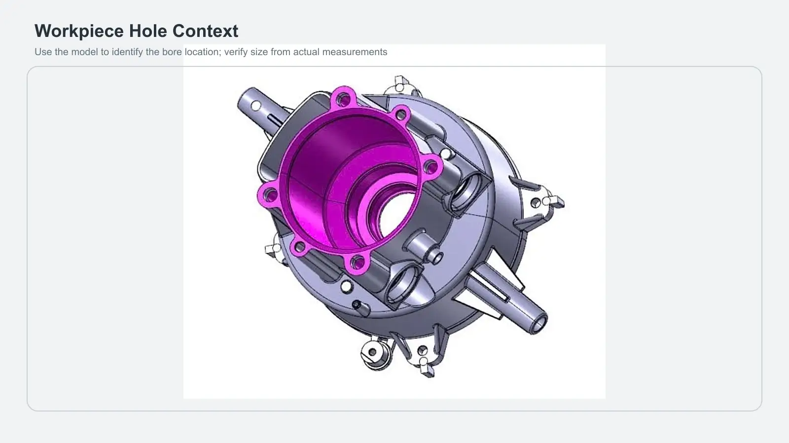
Stock allowance is application-specific. Too much can raise force, heat, deflection, and chip load; too little can promote rubbing or leave the reamer interacting with an inconsistent surface. Diameter, work material, reamer geometry, edge material, pre-hole quality, machine rigidity, and coolant delivery all affect the acceptable range. Set it from the selected toolmaker’s application data, then qualify it in the actual process.
If the finished feature requires meaningful correction of location or straightness, evaluate boring or another corrective operation before reaming. A reamer may slightly improve an existing hole under suitable conditions, but it is not a substitute for creating the required axis. The decision is process-based: prepare a hole the finishing tool can reliably size, or choose a process designed to correct the defect.
Measure the assembled tool, not just the loose reamer
A reamer can measure correctly on the bench and still run incorrectly in the spindle. Indicate the assembled system at the shank and as close to the cutting lead as access and safety allow. Rotate through a full revolution and repeat after cleaning and reseating. Follow the tool and holder manufacturers’ measurement locations and limits.
Inspect every interface: spindle taper or face, adapter, collet or hydraulic bore, chuck, shank, adjustment mechanism, and tool lead. Chips, dried coolant, burrs, fretting, worn collets, damaged seats, excessive stickout, or a bent shank can create runout or angular misalignment. A floating holder may accommodate limited alignment error in an approved application, but it does not erase a poor pre-hole, damaged tool, or unstable spindle interface.
Do not reduce runout to a single loose-tool reading. What matters is how the cutting edges orbit under the actual assembly and engagement. If cleaning and reseating changes the indication, keep that correction isolated and test it before changing speed or feed.
Read the cutting edges and chips
Clean the reamer only after documenting its as-found condition. Under adequate magnification, compare every lead edge and margin. Look for unequal wear, chipping, adhered material, polishing from rubbing, edge rounding, flute blockage, and marks that begin at one angular position. A single damaged or loaded edge can carry more of the cut and enlarge the effective cutting envelope.
Examine the chips and the finished surface together. Recut chips can score the bore and interfere with guidance. Packed chips or smeared material may point to flute loading, unsuitable geometry, poor evacuation, or insufficient lubrication at the cutting zone. A rough or torn surface with size growth suggests a different event from a uniformly smooth but oversize bore.
Through and blind holes create different evacuation constraints. Select flute direction, coolant path, and withdrawal strategy for the hole type, depth, and material behavior. Verify that chips have a viable exit path and that the selected fluid reaches the lead throughout the cut.
Change cutting conditions only after the mechanical checks
Once measurement, pre-hole, assembled runout, and tool condition are controlled, compare the programmed cutting data with the selected reamer manufacturer’s application guidance. Confirm units, actual diameter, work material and hardness, cutting-edge material, flute geometry, allowance, hole type and depth, coolant method, machine rigidity, and holder recommendation.
Avoid the familiar trap of applying one slogan—such as a fixed relationship to drilling speed and feed—to every reaming operation. Even useful starting rules become unsafe when detached from tool and application data. The accepted evidence includes source-specific examples and manufacturer ranges, but it does not support one universal setting.
Form a prediction before editing the program. For example: if thermal accumulation and rubbing are supported by edge and bore evidence, a qualified change should reduce that evidence as well as diameter error. Change only one input, run a test feature, and repeat the baseline measurements. If the expected response does not appear, restore the controlled baseline and move to the next supported hypothesis.
Decide whether to correct, recondition, or replace the process
Correct the setup when the failed verification identifies contamination, seating, alignment, stickout, approach, coolant access, or a program condition. Recondition, adjust, index, or replace a tool only when its design permits that action and inspection shows wear, damage, buildup, or size condition outside the qualified process. Do not grind, stone, or alter a precision reamer casually; uncontrolled edge modification can change diameter, lead geometry, load sharing, and surface finish.
If the tool family or cutting material is unsuitable for the work material, tolerance, volume, or wear mechanism, reselect the application rather than endlessly compensating the process. The Escariadores PCD page is a navigation point for identifying candidate PCD tool families after the material, bore geometry, tolerance, pre-hole, machine, and coolant conditions are defined. That product page is not proof that PCD is appropriate for every material or that a listed tool will correct an existing oversize bore.
Choose another finishing route when the real requirement is axis or form correction, when stock is outside the reamer’s qualified capability, or when the machine and setup cannot hold the necessary alignment. A professional forum incident involving an expensive stainless component shows how quickly an oversize result becomes a recovery problem; its reported dimensions and cutting data are case context, not settings to copy.
Release production only after a controlled confirmation
Run the corrected process on a test feature or sacrificial part when possible. Use the same material condition, pre-hole route, machine, holder, coolant state, and inspection method intended for production. Map the bore at the same depths and orientations as the failed feature, then check surface finish and any required form or location characteristics.
Require repeatability, not one favorable reading. Document the failed verification, the single correction, before-and-after measurements, tool and holder identity, program revision, and release authority. If the correction cannot be tied to an observed cause and repeated result, the process remains unqualified.
That discipline turns an oversize reamer event from trial-and-error adjustment into controlled troubleshooting: preserve the evidence, let the bore shape route the checks, correct one verified variable, and release only after the same measurement method confirms the result.