Ir al contenido
Small Insert Nose Radius: Forces, Stability, and Surface Finish Trade-Offs
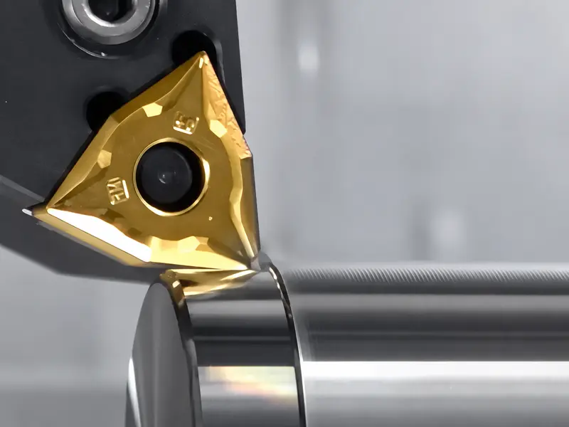
A small conventional insert nose radius is worth considering when setup compliance is the limiting problem. A long boring reach or a thin wall can react badly to added radial force, so reducing the radius may make the cut more stable. That is a trade-off, not a finish upgrade. The smaller corner is less robust, and a radius change alone does not prove that the resulting surface will improve.
Start by deciding what is actually limiting the cut. If the setup is rigid and stable and the goal is better theoretical feed-mark geometry, a larger radius can be attractive. If the tool, wall, or machine is moving, the same larger radius can increase the radial-load side of the problem. In either case, the answer still depends on insert geometry and hone, feed, depth of cut, material, wall support, and the real rigidity of the setup.
When is a small insert nose radius recommended?
The useful question is not “Which radius gives the best finish?” It is “Which trade-off fits this cut?”
| Dominant situation | What a smaller conventional radius can change | What it does not establish |
|---|---|---|
| A long boring reach or thin wall is compliance-limited | It can reduce radial loading and may make chatter less likely. | It does not guarantee a better surface finish or protect the smaller corner from breakage. |
| The setup is stable and theoretical feed marks are the main concern | Moving to a smaller radius may give away some theoretical finish latitude and corner strength. | It does not identify a universally correct radius. |
| The finish is unchanged after a radius change | It makes setup verification the next job. | It does not prove that nose radius was the original cause. |
This is why a small radius can help when a boring bar or thin wall deflects under radial load. On a rigid setup, a larger radius may instead offer the better balance of corner strength and theoretical feed marks.
Keep the finish-pass geometry compatible with the choice
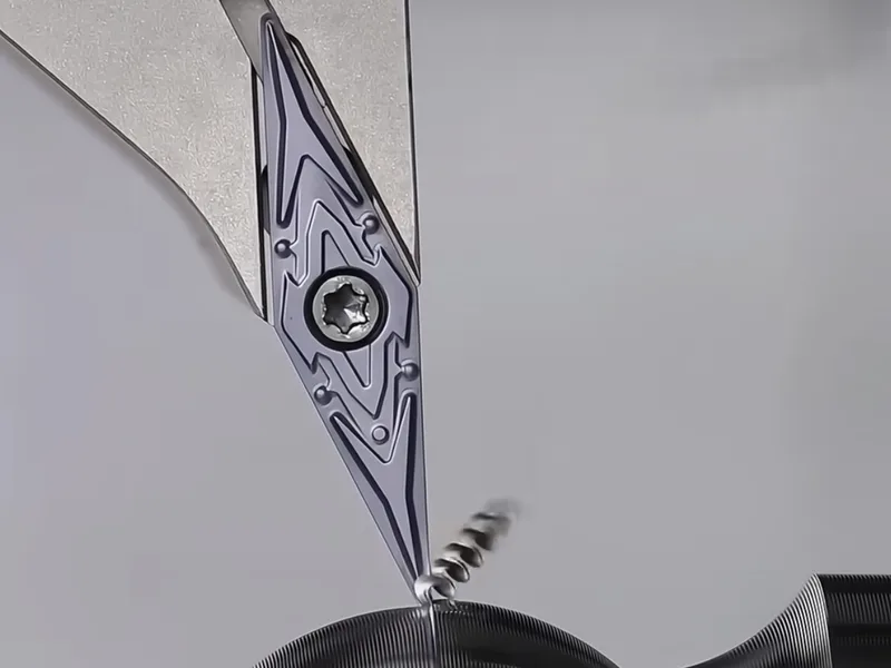
Changing radius without checking the finish-pass stock can create a different problem. Select the finishing allowance together with the nose radius, edge preparation, feed and workpiece support. Confirm that the remaining stock allows the selected edge to cut consistently under the actual setup conditions.
Keep radial depth of cut separate from stock on diameter. Radial depth is measured from the surface toward the center; stock on diameter describes the corresponding change across the diameter. Record which quantity the process sheet uses before setting the finishing pass. Check the allowance against guidance for the actual insert and material instead of assuming one ratio suits every turning or boring operation.
Treat theoretical finish as a limit, not a promise
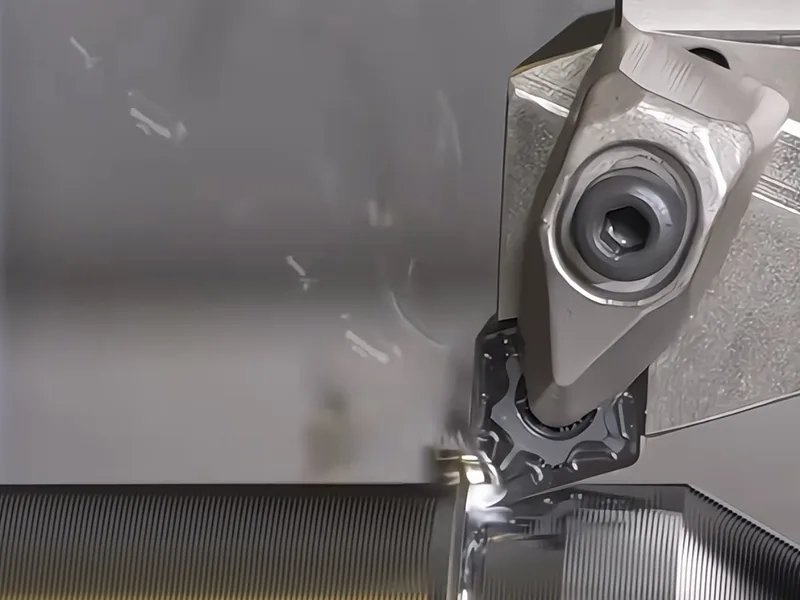
For a conventional rounded insert, a larger nose radius can reduce theoretical feed marks at a given feed. That geometric relationship helps compare options, but it does not guarantee the measured surface roughness. Wiper geometry changes the cutting-edge contact and requires its own application guidance.
Actual finish has more inputs than that geometry alone. Runout, edge condition, material behavior and vibration can override the expected pattern. Lowering feed also has a practical floor: the edge preparation and cutting conditions affect whether material is cut cleanly or rubbed. A smaller radius therefore does not make it safe to keep reducing feed until the surface looks right in theory.
If the finish does not change, stop treating radius as the root cause
Use a radius change as a controlled test. If the finish remains similar across reasonable radius and parameter changes, inspect the mechanical setup rather than assuming another radius will solve it. Check for movement in the toolholding, work support and machine interfaces using the applicable inspection procedure. An unchanged result is a reason to investigate those branches, not proof that a particular component is faulty.
For a practical check, hold the rest of the process as steady as the job allows, change one identified variable, and inspect whether the chatter or finish changes in the predicted direction. If it does not, return to setup rigidity, support, and contact conditions before treating the next radius as the cure.
Choose the trade-off, then prove it on the setup
Choose a small conventional nose radius when lower radial load addresses the dominant risk in the cut. Keep the finish-pass geometry compatible with that choice. Theoretical feed-mark geometry helps compare options; the actual setup still has to prove the result. If the finish does not respond as expected, inspect movement and support before trying another radius.