Skip to content
Cutting tool failure: causes and a practical troubleshooting guide
Cutting tool failure occurs when wear or damage prevents a tool from performing the intended cut reliably. It may develop gradually as the edge wears, or appear suddenly as chipping or fracture. The damaged tool shows what happened to the edge; it does not yet tell you whether the cause was the tool, the setup or the cut.
To find the cause, start with the damaged cutting edge and the point in the operation where the problem appeared. Then check the conditions that could have produced that damage. Changing feed or replacing the cutter before making those checks can leave the underlying problem in place.
Work through the checks in this order: tool damage, work material, machine and holding system, tool geometry and feature, coolant and chip evacuation, then actual cutting parameters. Establish the conditions in each group before deciding which need closer investigation. This keeps a missing setup detail from being mistaken for a feed or speed problem; it does not require every condition to receive the same depth of inspection.
1. Inspect the damaged tool and identify when it failed
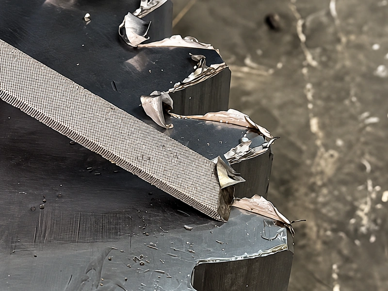
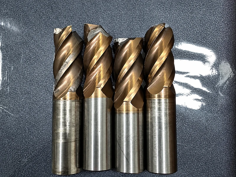
With the machine stopped and safe to inspect, look at the cutting edges, the damaged portion of the tool and the workpiece. Establish whether the edge wore progressively, lost small pieces, fractured, or collected adhered work material. Note the location: one edge, several edges, the tool tip, or farther along the cutting length.
Gradual wear is part of tool use. Check whether wear progressed predictably and whether the tool was changed before it stopped meeting the job’s requirements. A sudden fracture calls for a different investigation from an edge that steadily reached its wear limit. For a closer look at the patterns, see our guide to types of tool wear.
Compare the damage with the event: first contact, an interrupted feature, a change in engagement, or deterioration after a previously stable run. Photographs can preserve what you see for later comparison and help another engineer or the tool supplier assist with the investigation.
| What you observe | Checks to carry into the sequence below | What you are trying to establish |
|---|---|---|
| Small pieces missing from the edge | Interrupted contact, vibration, edge support and any adhered material | Whether the edge is seeing impact or instability, or losing material as an adhered deposit detaches. |
| A fractured cutter or large broken section | Clamping, tool reach, engagement, feed and depth at the failure location | Whether the actual cut placed a load on the tool that the setup could not support. |
| Wear progressing faster than on a comparable successful job | Material condition, cutting speed, effective feed and coolant delivery | Which condition differs from the successful process, and whether the tool still suits it. |
| Packed flutes, trapped chips or material adhering to the edge | Chip space, the feature being cut and delivery to the cutting zone | Whether chips are leaving the cut and whether adhesion needs a separate investigation. |
Use these observations to decide which checks need closer attention as you work through the sequence below. They do not establish a cause on their own. For example, chipping can result from impact, vibration or the detachment of welded material. The same visible loss of edge material can therefore lead to different corrective actions.
2. Verify the work material and its condition
Verify the actual workpiece grade, hardness and condition against what the tool was selected to cut. Include whether the part is cast, forged, quenched or tempered, and check any heat treatment rather than relying on the material name alone. If failures began with a new batch, investigate that batch’s condition. If damage repeats at a particular surface or region, check for a hardened area, hard spots, inclusions or casting defects that may warrant closer examination.
Record what is known and what still needs checking. A material designation does not confirm the condition of every part or every region within it. Carry any suspected local difference into the later checks of tool suitability and cutting conditions; do not treat it as a confirmed cause just because it coincides with the damage.
3. Check the machine, spindle and holding system
Next, identify the machine type, spindle operating speed and available spindle-load observations from the failure event. Note any change from a comparable stable run, including vibration or instability at an interruption.
Check the assembled setup before blaming the spindle
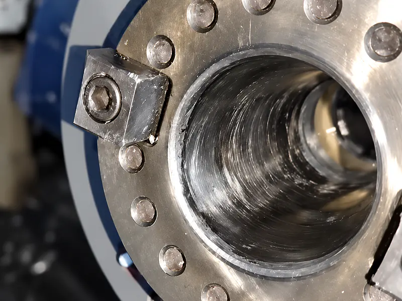
Inspect toolholding and workholding. Identify the holder type, such as hydraulic or shrink-fit, and use its specified clamping procedure. Check that the tool is seated and clamped as specified, that the workpiece is secure, and that the tool projects only as far as the operation requires. A longer reach introduced to clear a feature is a meaningful setup change even if the cutter and cutting data stayed the same.
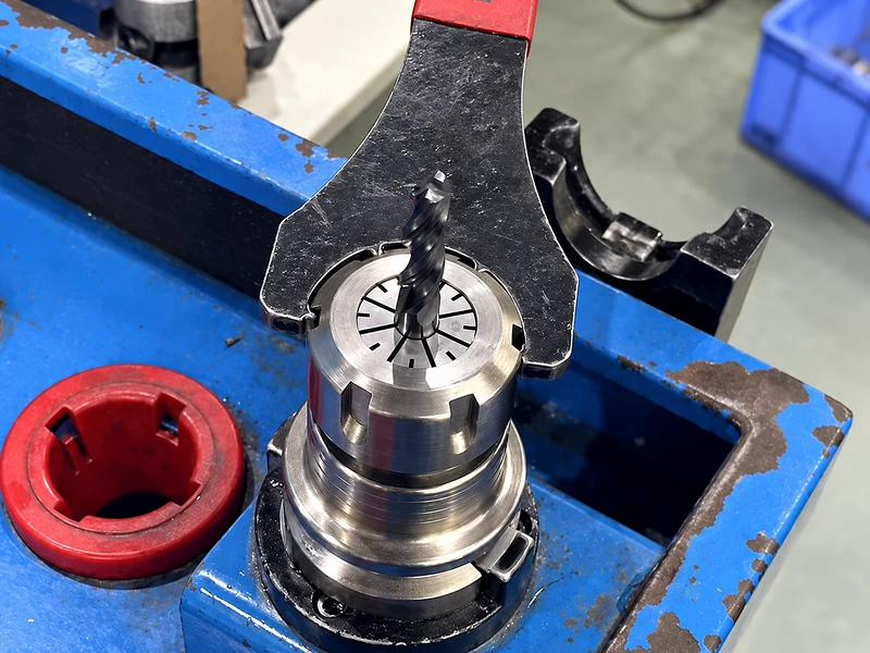
For an indexable tool, examine the insert seat and clamping components as well as the insert. Dirt or incorrect seating can compromise the installation; replacing only the damaged insert leaves that condition unresolved. Follow the toolmaker’s assembly and tightening instructions.
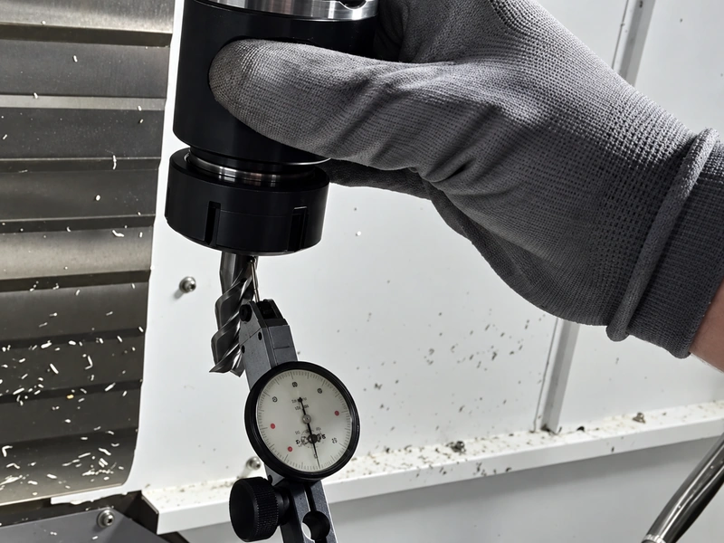
For a rotating tool, check assembled-tool runout with a suitable measuring method and compare it with the applicable tool and holding-system limits. Record the measurement position so the result can be repeated. Uneven damage is a reason to investigate, rather than proof that the spindle needs repair. When using solid carbide drills, include fixture and holder stability, radial runout and coolant supply when investigating edge damage.
Escalate unresolved runout with a repeatable measurement
If the basic setup checks do not resolve abnormal runout or instability, have a qualified technician distinguish tool, holder and machine contributions before changing the spindle or compensating with cutting parameters. For machines with a spindle taper, that investigation can include taper cleanliness and damage, followed by the machine maker’s prescribed taper or test-bar checks. Haas describes separate taper and precision test-bar measurements for its VMCs. Use the procedure and limits for the actual machine; a reading at the assembled cutting tool alone does not isolate a spindle fault.
4. Match tool geometry to the feature being machined
Check the actual feature against the tool’s intended application. In holemaking, distinguish blind and through holes and identify cross-holes or other interrupted regions. In milling, distinguish open side cutting from confined features and full-width engagement. Relate those features to the location and timing of the observed damage.
Then examine cutting length, flute geometry, flute count, edge geometry and the space available for chips. Check whether usable cutting length suits the depth and whether the design provides room for chips to leave the feature. If flutes are packed, review chip space and depth together rather than attributing the failure to tool grade alone. In end milling, small chip pockets and excessive cutting depth can both contribute to chip packing.
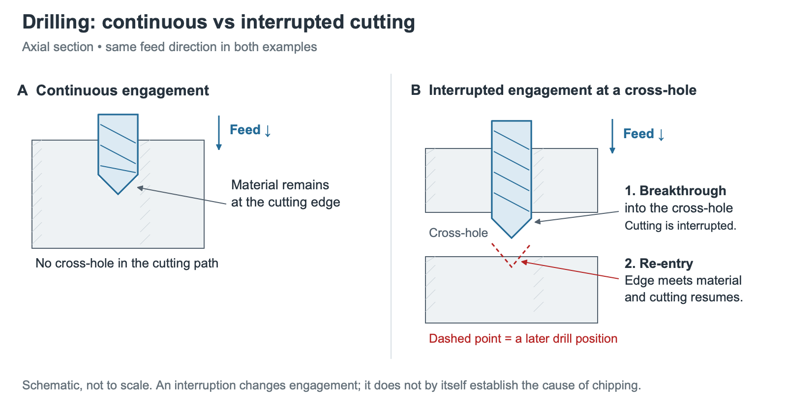
For repeated chipping at an interruption, check the selected edge geometry and support against the toolmaker’s guidance for that material and operation. Do not assume that a tool which works in a continuous cut is equally suitable at a cross-hole. If the application falls outside its intended use, confirm a suitable design before trying to compensate through feed changes.
Consider this hypothetical example. Two parts use the same steel grade and nominal hole diameter. A drill runs successfully in one, but chips repeatedly at the same depth in the other. The second part contains a cross-hole. Comparing only material, RPM and feed would miss the interruption. Inspecting the cross-hole location against the damage event directs the next check toward interrupted engagement, tool suitability and the programmed motion. It does not, by itself, prove that the cross-hole is the sole cause.
5. Check coolant delivery and chip evacuation
Inspect the chips and the space they must leave through. Look for retained chips in flutes or confined features, restricted evacuation, and adhered material on the cutting edge. Check that usable flute length and chip space suit the feature. Review the coolant method and delivery at the working area: internal or external supply, blocked passages, and misdirected nozzles where applicable. Where pressure is specified, verify the supply against the tool and machine requirements for this operation instead of assuming that a pump setting proves coolant reaches the cut.
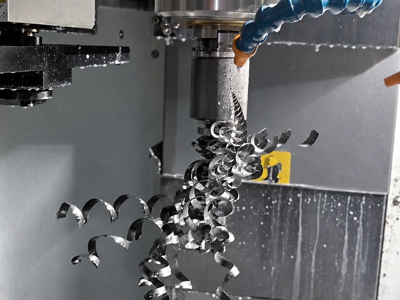
For drilling, chip control depends on the material, drill design and cutting conditions as well as coolant. In indexable drilling, poor evacuation can lead to breakage, while material and cutting data affect chip formation. Check those conditions for the actual drill and hole before changing the process. Increasing pressure or reducing feed is not a universal remedy. For repeated failures in holemaking, our drill breakage troubleshooting guide examines entry damage, deeper-hole failures and chip evacuation in more detail.
If you find a restriction, restore the intended chip path or delivery and inspect for tool damage before resuming. If evacuation is clear but work material is adhering to the edge, review geometry, cutting conditions and lubrication for that material. Chip packing and adhesion should not be treated as interchangeable problems.
6. Check the actual cutting parameters and motion
With the material, setup, tool and coolant conditions established, examine the actual operation around the failure location. Confirm spindle speed, feed and its units, depth of cut, and the entry or exit motion, including acceleration, deceleration or dwell. In milling, check feed per tooth against the actual RPM and flute count, and include radial engagement. In drilling, check feed per revolution against the actual RPM, together with the cycle and hole depth. Include any overrides used during the run.
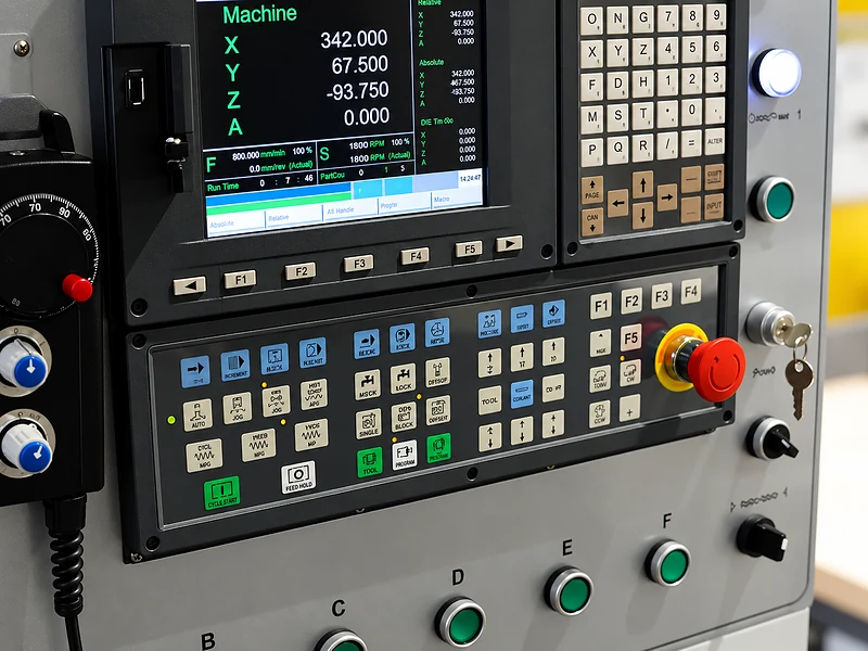
Look for a difference between the nominal settings and what the tool encounters. If an end mill fails at a transition into greater engagement, review that part of the path. If a tool is damaged at an interruption, inspect how it leaves and re-enters material. The same programmed feed does not describe every load condition along a path.
Compare those conditions with the toolmaker’s recommendations for the exact tool, material and operation. Correct an identified mismatch before the next trial. Avoid treating “reduce feed” as a universal answer: in end milling, excessive feed can contribute to breakage, while excessively low feed can contribute to peripheral wear. The damage and operating conditions determine which adjustment makes sense.
7. Verify the correction before returning to a full run
Use the next trial to test the suspected cause identified during inspection. If you found a clamping fault, correct it and verify the setup. If the failure coincides with an engagement change, review and correct that motion. If the material condition differs from the original setup assumptions, reassess tool suitability and cutting data for the actual condition.
Inspect the replacement tool and workpiece before the cutting time or part count at which deterioration was previously observed. For a new setup without that history, start with frequent checks and adjust the inspection interval from the observed wear. Compare edge condition, part quality, chips and relevant machine observations with the earlier run. A quieter cut or one successful part is useful information, but is not enough to establish stable tool life.
Keep track of the changes made together. If you replace the holder, change tool grade and reduce engagement at the same time, an improvement will not identify which change mattered. Where practical, isolate the suspected contributor while keeping the other conditions consistent.
Conclusion
Start with the damaged tool, then work through the material, machine and holding system, tool geometry and feature, coolant and chip evacuation, and finally the actual cutting parameters. Establish the full picture before narrowing the investigation. The aim is to identify a condition you can verify and correct, then confirm that the correction holds up in the next trial.
If the cause remains unclear, contact Sunditools with photos of the damage, where and when it occurred, relevant measurements and the changes already tested. Our team can review that evidence with you to decide whether the next trial should address tool geometry, cutting tool material or machining conditions. For a suspected machine fault, involve your machine specialist as well.