Skip to content
Drill Breakage: Find the Cause of Repeated CNC Drill Failures
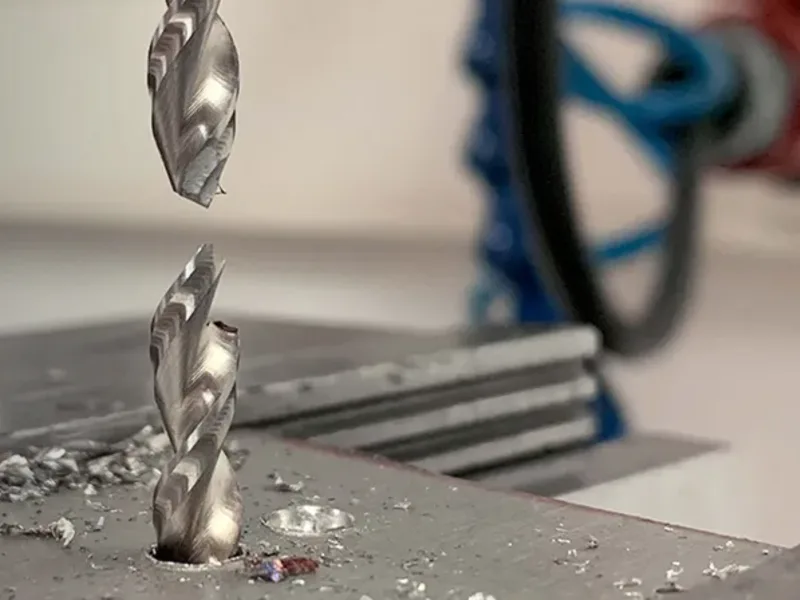
When a drill breaks, stop the cycle and preserve the evidence. Keep the failed tool, the chips from that hole and the workpiece if possible. Record whether the failure happened on entry, while the drill was established in the hole, at breakthrough or during retract. Photograph the cutting edges, flutes, entry and exit before cleaning anything.
That first record is more useful than an immediate feed or speed change. A drill breakage root cause is often a chain: runout can load one edge, poor coolant delivery can slow chip evacuation, and a peck or breakthrough event can supply the final shock. The break location tells you where to start checking. It does not prove one cause.
Start with what happened, not a favorite cause
For CNC drill breakage, use the failure event to choose the first inspection. Check the physical evidence before settling on a cause.
| What you observed | Check first | Plausible branches, not a verdict |
|---|---|---|
| The drill broke at first contact or inside the spot | Entry surface, spot/point relationship, outer corners, workholding and measured concentricity | Uneven first contact, damaged edge, point mismatch, interrupted contact, runout or weak clamping |
| It broke after reaching depth or after several holes | Chips in the flute and hole, actual coolant path, usable flute length, edge condition and runout | Chip packing, blocked or misdirected coolant, insufficient clearance, progressive damage, runout or harmful re-entry |
| A flute is visibly loaded, split or smeared with chips | Retained chips, chip form before and near failure, coolant at the tip and edge condition | Packing and recutting, a restricted chip path, coolant-delivery failure or a changing cutting condition |
| A small carbide drill fails suddenly | Tool, collet/holder and spindle interfaces, then measured concentricity | Runout, angular error, dirt or damage at an interface, brittle impact, edge damage or chip loading |
| It fails at breakthrough or on retract | Exit side, workholding, attached web or slug, trapped chips and event timing | Exit shock, part movement, unsupported exit, flute binding or earlier damage |
| Breakage starts after a stable run | Last good versus first failed hole, chips, edge, coolant, interfaces and alignment | Progressive wear, chip/coolant drift, contamination, loss of alignment or workpiece movement |
The rest of the guide follows those observations. Each branch ends with a check that can support or weaken it. If the check does not support the suspected cause, do not keep tuning that branch.
Why did the drill break on entry?
Treat an early failure as an entry and setup problem first. An uneven, hard or interrupted surface can load the point unevenly. A spot that does not suit the drill point can bring an outer corner into contact before the drill is properly guided. Damaged cutting edges, workpiece movement, runout, angular error and poor clamping can produce the same early timing.
What would confirm the branch?
Preserve the entry mark and inspect the surface and spot. Look at the drill point and both outer cutting corners for pre-existing damage or unequal contact. Check that the workpiece did not move. Clean the toolholding interfaces, then measure concentricity at the tool and isolate holder or spindle contributions if the first reading is not acceptable for the specific drill and process.
Keep surface condition, bore depth, material and usable tool length in the inspection record. For first-contact failures, compare interrupted contact, concentricity, angular alignment and clamping before changing cutting data. The inspection identifies which condition needs correction; it does not supply settings for a different drill or application.
Corrective action and boundary
Correct the condition you actually found: repair the entry surface or spotting method, restore workholding, clean and reseat the interface, correct alignment, or replace a damaged drill. Review the entry motion only after those checks.
Why did the drill break deeper in the hole?
If the drill survives entry and fails later, inspect chip evacuation and coolant delivery before assuming the programmed speed is the problem. Depth-sensitive failures can also come from insufficient usable flute length, progressive edge damage, runout, or a retract and re-entry motion that adds contact or impact.
What would confirm the branch?
Inspect the failed flute and recover chips before clearing the hole. If it is loaded with chips, follow the packing checks in the next section. Verify that coolant reaches the cutting zone; pump-on status does not prove delivery at the tip.
Next, confirm hole depth against usable flute length and overall tool length. Inspect the cutting edge, measure runout and review the cycle for dwell, full withdrawal, rubbing or abrupt re-entry. This order separates a chip-path problem from a mechanical or motion problem.
Corrective action and boundary
Route the correction to the evidence. Restore chip or coolant flow if the flute is loading. Correct measured runout or interface damage before changing the cutting data. If the failure aligns with peck or re-entry, review that motion for the exact drill and coolant arrangement.
Failure depth selects the inspection order; it is not a cutoff that proves chip packing.
Do the chips and coolant point to packing?
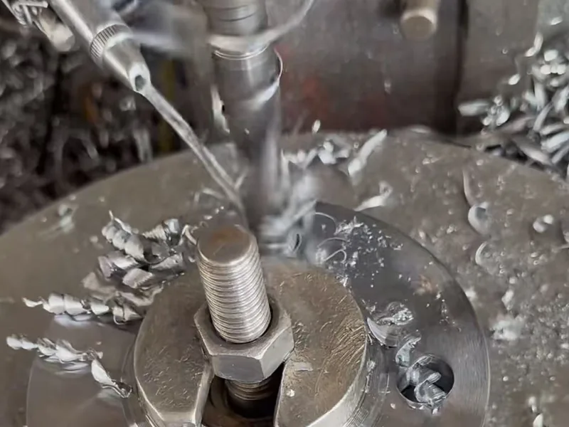
Chip shape, flute loading and coolant delivery form one diagnostic set. Color alone is not enough. When chips are produced faster than they leave the flute, they can pack and be recut. Research on chip-evacuation forces and clogging examines how this restriction increases drilling load. Torque and radial load rise, and a flute or brittle carbide body may then fracture.
What would confirm the branch?
Photograph a loaded or split flute before cleaning it. Recover chips from the flute and hole, then compare their length, curl, nesting and consistency with chips from a stable hole. Inspect the cutting edge for damage or build-up. Trace the coolant route to the tip and check for a blocked duct, misdirected nozzle or filtration problem.
Chip temperature or color alone cannot establish whether evacuation is adequate. Assess chip length, curl, nesting and flute loading together with coolant delivery at the cutting zone. Choose the cooling or lubrication method for the actual drill, material and hole geometry, then verify that chips leave the hole consistently. A cooler-looking chip is not proof of a clear chip path.
Corrective action and boundary
Remove the confirmed restriction. Restore directed coolant or air where the tool and process permit it, clear a blocked path, or correct the chip-formation problem using the toolmaker’s conditioned guidance. Run one verification hole and inspect the chips again.
A packed flute supports a packing diagnosis, but it still does not reveal which upstream condition caused the packing. Avoid copying pressure, feed or speed from an unrelated shop case.
Could runout, the holder or the spindle be breaking the drill?
Measure concentricity before tuning the process when a small drill fails suddenly, the outer corners wear unequally, hole size or position changes, or breakage begins after a tool or holder change. Runout can load one cutting edge more than the other. Dirt, damage or angular error at any interface can create a similar result.
What would confirm the branch?
Inspect the cutting edges first. Clean and inspect the collet or holder, taper, end face and spindle interface. Look for deposits, pressure marks or damage. Measure at the cutting tool with resolution suitable for its diameter, then use holder and spindle checks to isolate the source. Verify clamping and alignment instead of accepting a nominal holder specification as evidence.
Corrective action and boundary
Repair or replace the damaged interface, restore clamping, clean and reseat the tooling, or correct the measured alignment problem. Confirm the tool runs as required before drilling another hole. Only then return to chips, coolant and cutting conditions.
Use the runout limit specified for the drill, holder and operation; small drills are particularly sensitive to eccentric loading.
Did pecking or re-entry help evacuation or add impact?
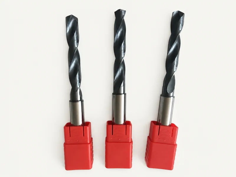
Pecking is conditional. It may restore chip evacuation when coolant delivery or flute clearance cannot support a continuous cut. It can also add dwell, wall contact, full re-entry or impact that damages a brittle microdrill. A through-coolant geometry may need a different cycle from an externally cooled tool.
What would confirm the branch?
Identify the exact motion at failure. Did the tool break during continuous cutting, on retract, at re-entry or after a dwell? Inspect the retained chips and flute loading. Verify the coolant method and drill geometry. Review retract distance, clearance, dwell and feed-back-in behavior against the toolmaker’s instructions for that diameter, L/D, material and machine.
Corrective action and boundary
Choose continuous drilling or a conditioned peck/retract strategy only after those checks. Change one part of the motion and run a controlled verification hole.
A cycle that clears chips in one setup can add damaging contact in another. Validate peck depth, retract distance and re-entry for the actual tool, hole depth and coolant arrangement rather than adopting a default full-retract or no-peck rule.
Why did it fail at breakthrough or on retract?
If failure occurs as the point exits or while the drill retracts from a through-hole, inspect the exit side and workholding first. Plausible branches include exit shock, a thin remaining web or attached slug, part movement, unsupported exit and chips binding along the flute. Runout or damage that began earlier can still be involved.
What would confirm the branch?
Confirm the event timing from the program, spindle-load trace or direct observation. Inspect both sides of the hole. Look for an attached web or slug, an irregular exit, trapped chips and any sign that the workpiece moved. Inspect the drill for damage that may have existed before breakthrough. Measure runout if the physical evidence does not separate the branches.
Corrective action and boundary
Stabilize the workpiece and exit condition, clear the chip path, and review the breakthrough and retract motion against guidance for the exact tool. Test the corrected exit phase separately from other changes.
Why does the drill keep breaking after a stable run?
Compare the last good hole with the first failed hole. A once-stable process can change because the edge is damaged, flutes gradually load, coolant or filtration drifts, an interface becomes contaminated, alignment changes, clamping weakens or the workpiece moves.
What would confirm the branch?
Place the chips, hole condition and tool-edge evidence from the two points side by side. Check coolant delivery and filtration. Clean the interfaces and repeat the concentricity checks at the tool, holder and spindle. Verify clamping and workpiece position.
A previously stable run does not rule out later alignment or workholding changes. Re-measure the setup when the evidence points to movement or unequal loading; do not assume every delayed failure requires machine repair.
Corrective action and boundary
Repair the verified tool, coolant, interface, alignment, clamping or workholding condition. Re-establish a measured baseline and run one verification hole before retuning the process.
Follow this root-cause sequence before changing more variables
Checks that require no tool or process change
- Stop the cycle and preserve the failed drill, chips and hole.
- Record whether failure occurred at entry, in the established cut, at breakthrough or on retract.
- Photograph the point, cutting edges, flute, entry and exit before cleaning.
- Check for workpiece movement, visible flute loading, an attached exit web or slug, and actual coolant delivery.
- Compare the last good hole with the failed hole and review the event timing.
Checks that require measurement or disassembly
- Inspect the point, outer corners and flute for damage or build-up.
- Clean and inspect the collet or holder and spindle interfaces.
- Measure tool concentricity and isolate holder, spindle or alignment error with suitable resolution.
- Verify coolant ducts, flow path, pressure at the relevant point and filtration.
- Confirm usable flute length, overall tool length, hole depth and workholding.
Changes to process or tooling
- Use the confirmed mechanism to choose one correction: restore chip/coolant delivery, correct alignment or clamping, repair the entry or exit condition, or revise the cycle according to the toolmaker’s guidance.
- Run one controlled verification hole and inspect the tool and chips again.
- Only then adjust conditioned speed, feed or cycle values. Change one variable at a time and record the material, drill geometry and diameter, L/D, machine, holder and coolant system.
Drill breakage root-cause checklist
- Stop and preserve evidence. Keep the failed drill, chips and workpiece. Record when the failure occurred.
- Choose the inspection branch. On entry: surface, point relationship, clamping and runout. Deeper in the hole: flute loading, coolant and usable flute length. At breakthrough or retract: exit condition, support and binding.
- Confirm the suspected mechanism. Inspect the edge and retained chips; measure alignment or runout where the evidence calls for it.
- Correct the condition you found. Restore chip or coolant flow, repair the setup, or revise the motion for the specific tool and hole.
- Verify one change. Run a controlled test hole and inspect the tool and chips again before changing another variable.