



CUSTOM THROUGH-COOLANT REAMERS
Custom Carbide Reamers for Blind Holes
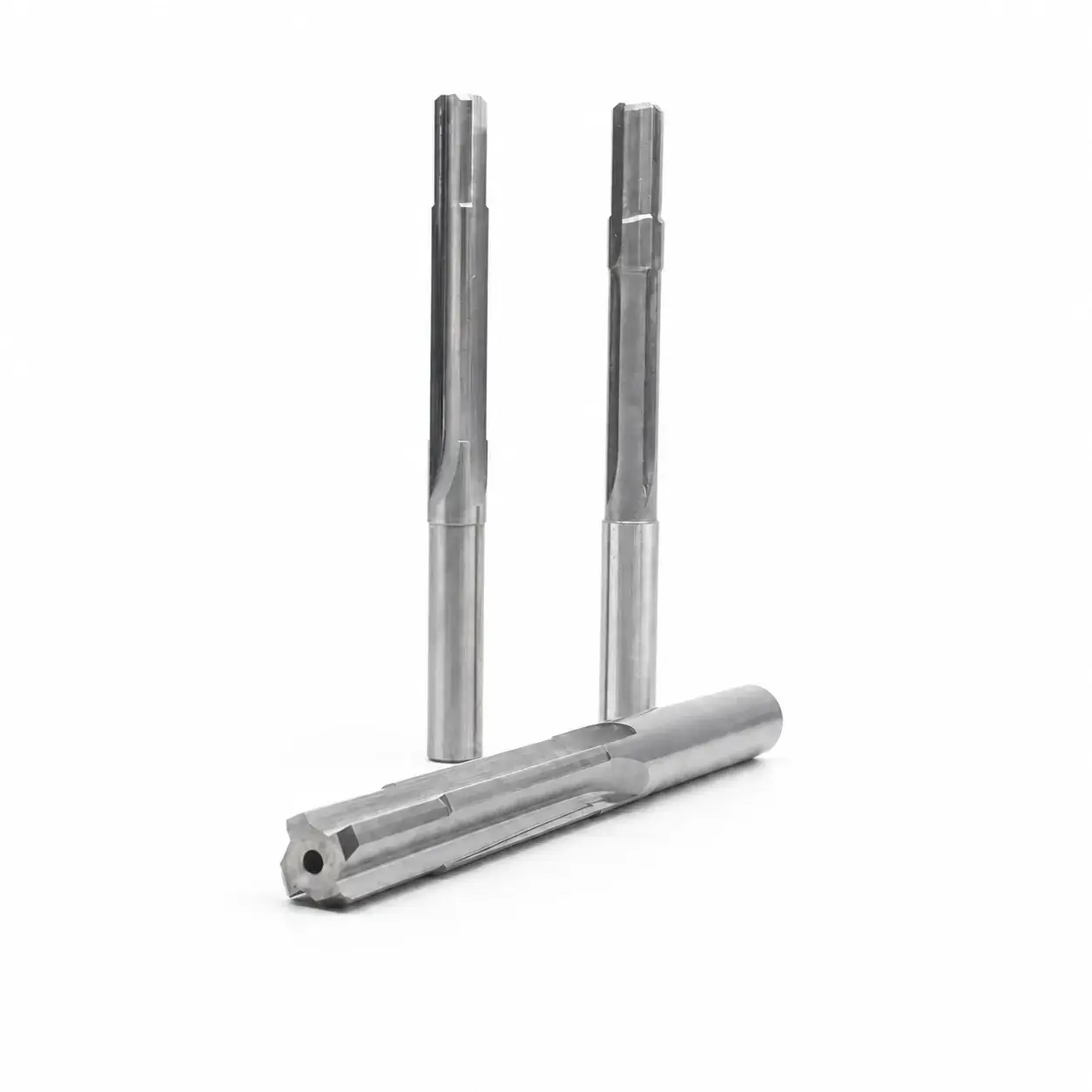
Blind-hole reaming requires coolant and chips to return through the same opening. SCT engineers the centre-through coolant passage, flute geometry and margin design around the bore depth, workpiece material, pre-hole condition and the machine’s available coolant pressure and flow.
Choosing Coolant and Geometry for Blind Holes
- Coolant passage
- Sized around available pressure and flow
- Flute helix and unequal spacing
- Available for deeper-hole stability
- Margin width and cutting geometry
- Matched to material and finish requirements
To Get Started:Share the drawing, material, pre-hole, finished tolerance, hole depth and coolant conditions.
- Confidential drawing review
- Specification approved before grinding
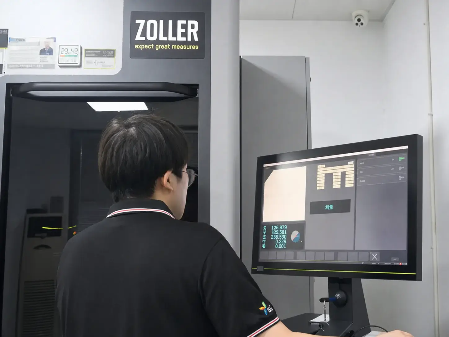
- Walter grinding & Zoller inspection
- Inspection report supplied
ENGINEERING REVIEW BEFORE PRODUCTION
We Set the Blind-Hole Process Before Grinding Starts
The tool is designed around how coolant enters, how chips leave and what the finished bore must achieve—not around a catalogue diameter alone.
DEFINE THE BORE
Define the Finished Bore
Confirm diameter, tolerance, surface finish, depth and the usable bore bottom.
PRE-HOLE ALLOWANCE
Set the Pre-Hole Allowance
Match the incoming bore and stock to the material, cutting edges and required bore result.
COOLANT & CHIP FLOW
Plan Coolant and Chip Evacuation
Specify centre-through coolant, pressure, flute direction and available chip space.
COMPLETE SETUP
Check the Complete Setup
Review holder, runout, reach, fixture clearance and the production inspection target.
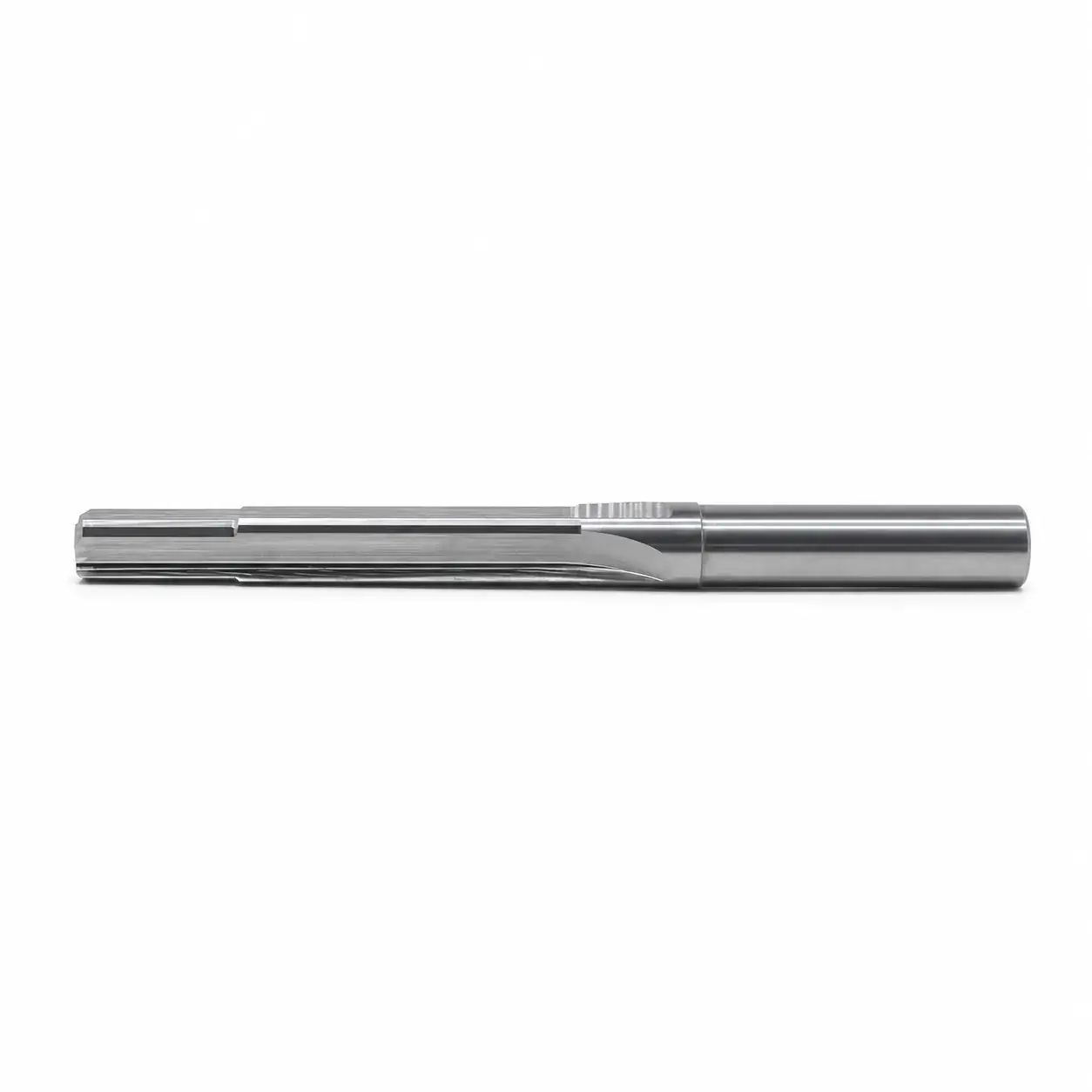
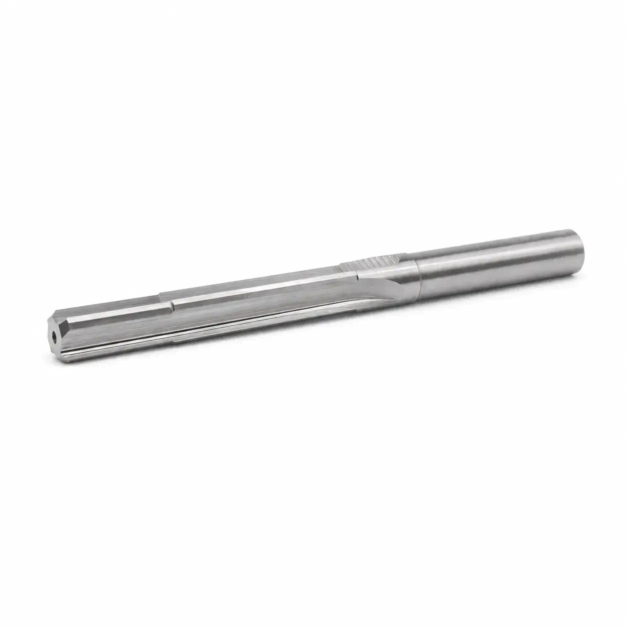
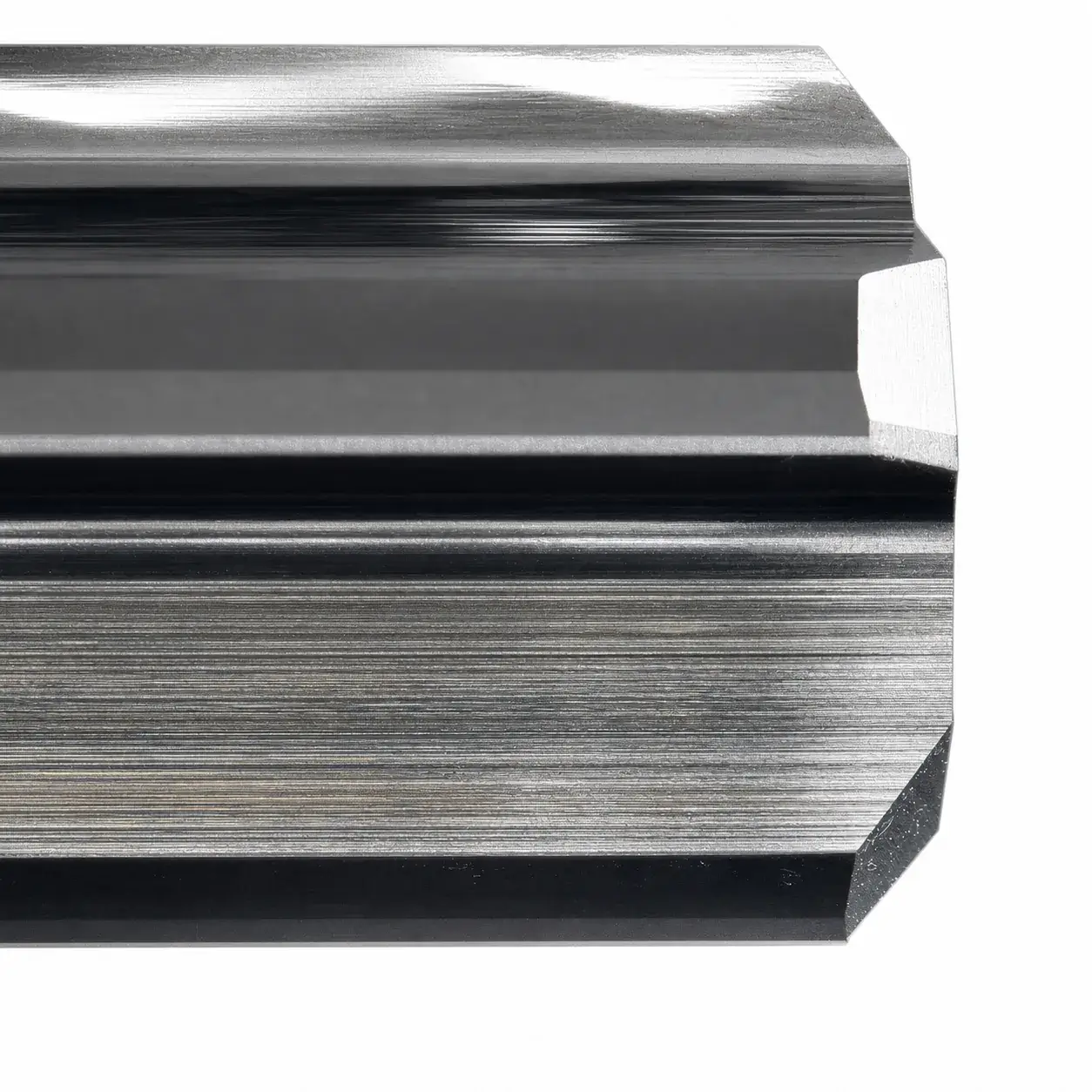
Side profile, centre-through coolant outlet and inspected cutting-edge detail.
PRODUCTION AND QUALITY CONTROL
From Released Blind-Hole Specification to Ground Geometry
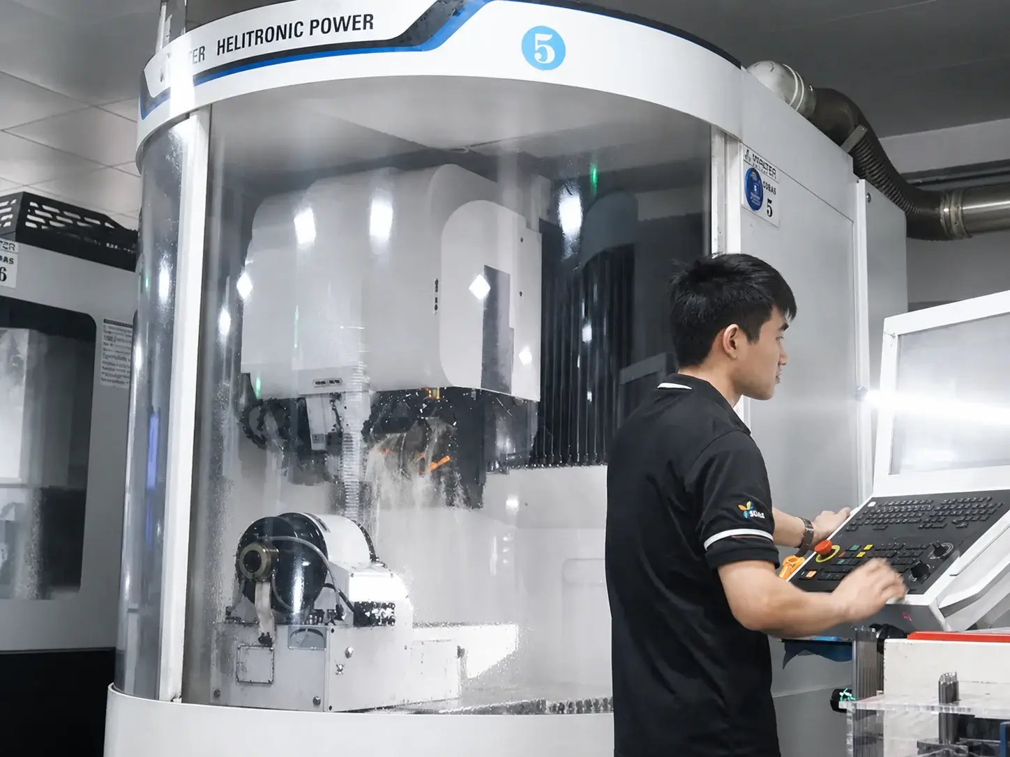
We verify the blank, grinding program, wheel setup and dimensional references before producing the approved flute, margin and cutting-edge geometry.
Prepare the Grinding Job
Verify the carbide blank, coolant-channel position, program, wheel setup and released dimensional references.
Grind the Application-Specific Geometry
Produce the specified flute helix, unequal spacing where required, margin geometry, cutting edges and finished dimensions.
QUALITY CONTROL DURING AND AFTER GRINDING
Measure During Production. Release After Final Inspection.
We measure critical dimensions and geometry during grinding, correct measurable deviation while adjustment remains possible, and complete final inspection before release.
Measure and Correct During Production
Check finished diameter, cutting length, runout and specified geometry while measurable correction remains possible.
Final Inspection and Release
Record the specified results and release the tool only after the approved inspection criteria are met.
BLIND-HOLE REAMING REVIEW
Start with the Bore and Coolant Conditions
Send the drawing, material, pre-hole, finished diameter, hole depth and available coolant pressure. We will review whether a centre-through-coolant carbide reamer is suitable for the application.
Drawings and uploads are treated as confidential project information.