


CAD vs CAM: Understanding the Core of Digital Manufacturing
Software used in manufacturing is driven by several key technologies, including CAD, CAM, CAE, and PLM. Each of these technologies plays a key role in optimizing product development and manufacturing processes. While these technologies often work hand-in-hand, their roles and their impact on workflow are distinctly different. As an engineering, architecture, or design professional, it is important that you understand the differences between CAD and CAM.
In this article, we will be discussing the core fundamentals of CAD and CAM, from practical applications to key defining differences. Keep reading to understand how using the right tools at the right time can significantly improve the development process of your products.
Contents
What is Computer-aided Design (CAD)?
Before you can create a physical product, you must first have it as an idea and then as a detailed plan. Computer-aided design (CAD) is the technology that helps you transform these ideas into actual digital designs. It is the first and fundamental step in the modern manufacturing workflow.
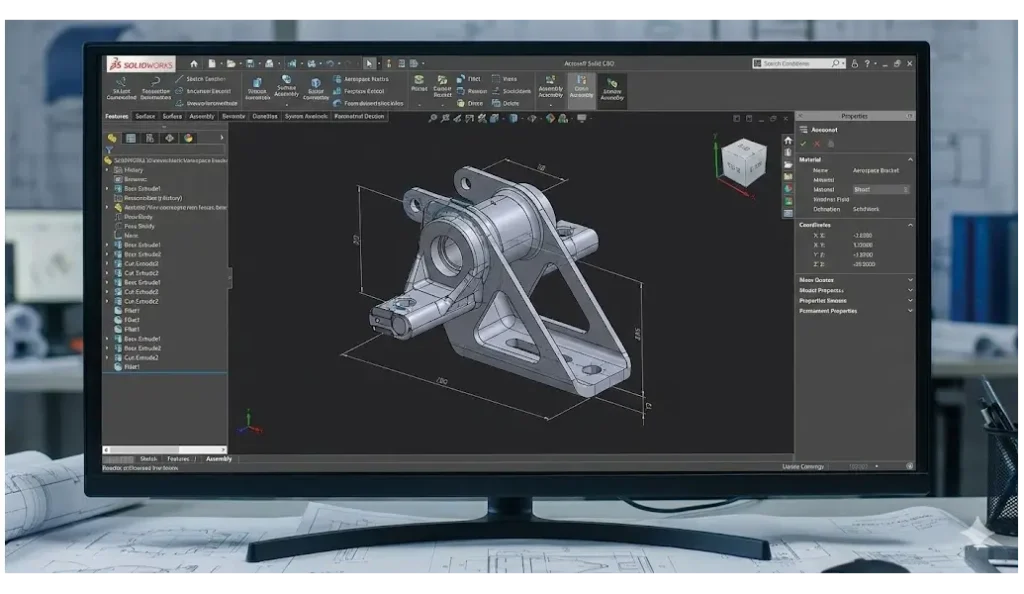
CAD is simply the use of computer systems to assist in the creation, modification, analysis, or optimization of a design. In the Computer-aided design software digital space, ideas take shape and come to life. This software gives you an arsenal of tools to use for drawing, 3D modeling, annotating designs, and adding precise dimensions. Engineers and drafters, for instance, make use of CAD for creating all kinds of designs, from simple 2D illustrations to complex 3D models.
Manufacturing needs an adequate design definition, but not every job requires a complete 3D model. Depending on the process, 2D geometry, drawings, or other validated specifications may be sufficient.
With CAD, designers and engineers are able to visualize and modify their designs accurately, facilitating the development of complex products and systems.
Why is CAD Important?
The importance of CAD goes far beyond simply turning an idea into a digital format; it radically changes the design and prototyping phase involved in product development. By creating a complete digital definition of a product, CAD has successfully opened up new levels of precision, optimization, and collaboration.
CAD makes digital revisions easier and can reduce physical prototyping, but changes still require engineering time, validation, and sometimes additional software or production costs.
As a programmer, CAD allows you to observe a design experiment with its proportions, materials, and complex geometries. This makes it possible to truly optimize a component without wasting physical material during prototyping. With computer-aided design, you can create extremely detailed and precision-focused models, perfectly aligned with specifications.
Furthermore, models are no longer tied to physical copies that can be lost or damaged. When using CAD, you can duplicate files and share them as many times as you want. Many manufacturers upload their files to cloud storage so that employees and subcontractors can access them whenever they need them. This improved collaboration and data management is crucial.
Practical Applications of CAD
CAD is proven to be a very versatile technology, offering incredible precision, making it an indispensable tool across a wide range of industries. CAD serves as the foundation for both creative and technical projects. From soaring skyscrapers to microscopic electronic components, CAD provides the essential framework for design and innovation.
In digital manufacturing, it is crucial to understand the practical applications of CAD; this knowledge is invaluable. Its precision is crucial in industries such as aerospace, automotive, and electronics, where even the smallest error can lead to significant functional complications. What are some of the most common applications of CAD?
- Architecture: CAD is used to design and visualize buildings and structures. This gives architects the creative freedom to create detailed floor plans and designs.
- Engineering: CAD supports mechanical part and assembly design. Physical-performance testing generally requires suitable CAE or simulation capabilities and validated inputs.
- Industrial Design: Designers use CAD to create consumer products, machinery, and tools that meet both aesthetic and functional standards.
- Urban Planning: CAD supports layout and infrastructure drawings; traffic or other system simulations require appropriate specialist tools.
What is Computer-aided Manufacturing (CAM)?
Once a design is finalized in CAD, the next step is to transfer that digital design to the physical world. This is the domain of Computer-Aided Manufacturing (CAM), the technology that serves as a fundamental bridge between design and manufacturing.
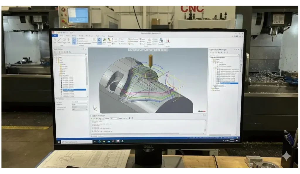
Computer-Aided Manufacturing (CAM) prepares manufacturing operations from suitable 2D or 3D geometry. Some systems include basic CAD tools; programmers still define stock, tools, setups, and cutting conditions, then use an appropriate postprocessor for the target machine.
CAM helps plan cutting strategies and operation sequences. For computer numerical control (CNC) machining, it typically generates a program through a suitable postprocessor; the machine controller executes that program.
Why is CAM Important?
CAM helps convert design intent into manufacturing operations. Finished-part conformity still depends on the setup, machine, tools, process, and inspection.
CAM is especially valuable for complex toolpaths, but CNC programs can also be written manually or with conversational programming.
CAM software bridges the gap between design and manufacturing. It converts CAD models into CNC instructions, such as G-code and M-code, serving as a guide for every movement of the machine’s tools.
CAM can check selected toolpath and collision conditions represented in its model; it cannot detect every manufacturing error or guarantee ideal speeds and feeds. Programmers must verify the setup, postprocessed code, and process conditions.
Using these instructions, a wide range of processes can be controlled, including:
- Milling
- Lathing
- Routing
- Laser cutting
- Grinding
- Robotic actions
Practical Applications of CAM
CAM technology is the driving force behind a wide range of automated manufacturing processes. It directs the high-precision production of components across a number of industries. The ability of CAM to translate digital designs into mechanical actions makes it an indispensable part of modern manufacturing.
CAM supports CNC production of metal and plastic components. For injection-mold tooling, CAD defines mold geometry and CAM can program its machining; the molding machine controller manages the molding cycle.
Some of the practical applications include:
- Machining: Operators employ CAM to program CNC machines for milling, turning, and grinding metal and plastic components with high precision.
- Injection molding: CAM helps program machining of molds designed in CAD; it does not by itself design the mold or control every injection-molding process.
- Woodworking: CAM systems in woodworking automate the cutting, shaping, milling, and assembly of wooden components.
- Additive Manufacturing: CAM supports 3D printing processes by slicing a 3D model and generating layer-by-layer instructions for material deposition.
Key differences between CAD and CAM
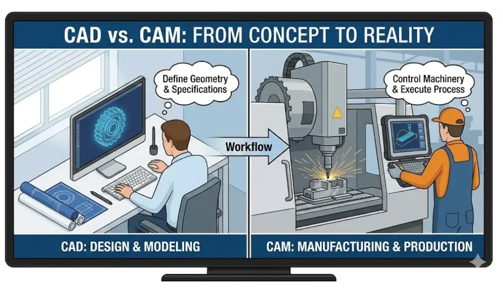
Despite the fact that CAD and CAM are deeply connected, and when one gets spoken about, the other always gets mentioned too, their core functions are ultimately different. This fact can be really confusing due to the similarities that exist between them, but understanding their differences is crucial to appreciating how they form such a powerful partnership.
In simple terms, CAD is responsible for the design and illustration of a product, while CAM is responsible for its manufacturing. The engineering blueprint that you create in CAD is translated by CAM into machine language (usually G-code and M-code). When the codes get transmitted to a CNC machine, the machine instructs its tools to perform the machining as required.
The synergy between the two streamlines modern engineering tasks, but their difference underscores the fundamental shift from conceptualization to implementation. Typically, CAM software is often less generic than CAD. Highlighted in the table below are some key differences between CAD and CAM:
Context | CAD (Computer-Aided Design) | CAM (Computer-Aided Manufacturing) |
Primary purpose | Product design, engineering documentation, data management | Manufacturing process planning and optimization |
Main users | Design engineers and product developers | Manufacturing engineers, CNC programmers, and machinists |
Core functions | 2D/3D geometry and technical documentation; engineering analysis requires suitable CAE capabilities | Process planning, toolpath generation, G-code creation |
Output | Complete digital product definition (3D models, 2D drawings) | Optimized manufacturing processes and machine instructions |
Skills required | Design principles, engineering analysis, and software proficiency | Manufacturing processes, tooling, and CNC programming |
Software examples |
Why You Should Combine CAD and CAM for Your Project
While they are built to perform different tasks, CAD and CAM work best when used in complement of each other. The synergy between these two software creates a streamlined, efficient, and highly accurate workflow, helping to elevate your project from a mere idea to a finished physical product.
CAD supplies geometry for CAM process planning and toolpath generation. A suitable postprocessor produces machine-specific instructions. Data exchange must be checked for units, geometry, revisions, and other information that may not transfer correctly.
Some developers even offer combined CAD/CAM systems that integrate the entire process in a single environment. Using software that can be easily paired or combined is the key to fast, simple, and profitable production.
The combination of CAD and CAM technologies offers several advantages, and they:
- Greater precision: CAD/CAM systems help keep human errors at its most minimal by providing precise measurements and automated processes.
- Greater efficiency: Automation and digital design streamline workflows, speeding up the design-to-manufacturing cycle.
- Cost effectiveness: By promptly identifying design flaws and optimizing toolpaths, most possible material wastes and production costs get reduced.
- Improved collaboration: Team members can easily share and edit files, facilitating a more integrated and collaborative workflow between design and manufacturing teams.
Bottom Line
CAD and CAM software support design and production planning, but machine setup, data transfer, and generated programs still require validation. Industries such as aerospace use these tools to prepare complex, precise components.
These software offer rapid prototyping, develop products faster, and reduce material waste. However, the effectiveness of the most advanced CAD/CAM software and CNC machine is only as effective as the cutting tools executing the code.
To achieve the highest precision in your digital designs, you need industrial-grade tools that can meet the demands of modern high-speed manufacturing. This is where Sundi Precision Tools comes in. We are the most reliable link between computer-aided design and manufacturing reality.
We provide a comprehensive catalog of high-performance CNC milling cutters, premium carbide blades, and advanced drill bits designed for full precision.
Whether machining a titanium component or wooden parts, suitable tooling must be combined with correct programming, setup, and cutting conditions; no tool guarantees that every command produces a flawless, burr-free cut. Reach out to discuss tooling for your process.