




Velocidade de corte de alargadores PCD: validar o dado antes de calcular RPM
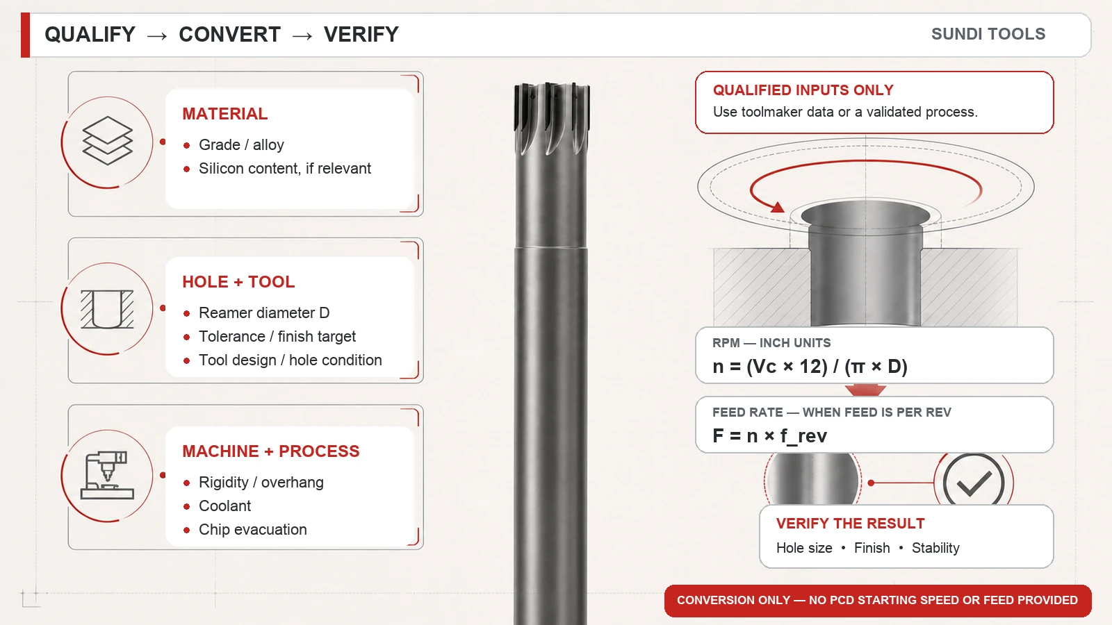
Não escolha a velocidade de um alargador PCD numa tabela genérica. Confirme material e liga, diâmetro, tolerância e acabamento pretendido, além de rigidez, refrigeração, evacuação e conceção. Converta depois uma velocidade periférica validada em RPM. Calcule o avanço linear apenas se os dados validados definirem avanço por rotação. As evidências aceites para esta página não fornecem um valor inicial universal de velocidade ou avanço por rotação para PCD.
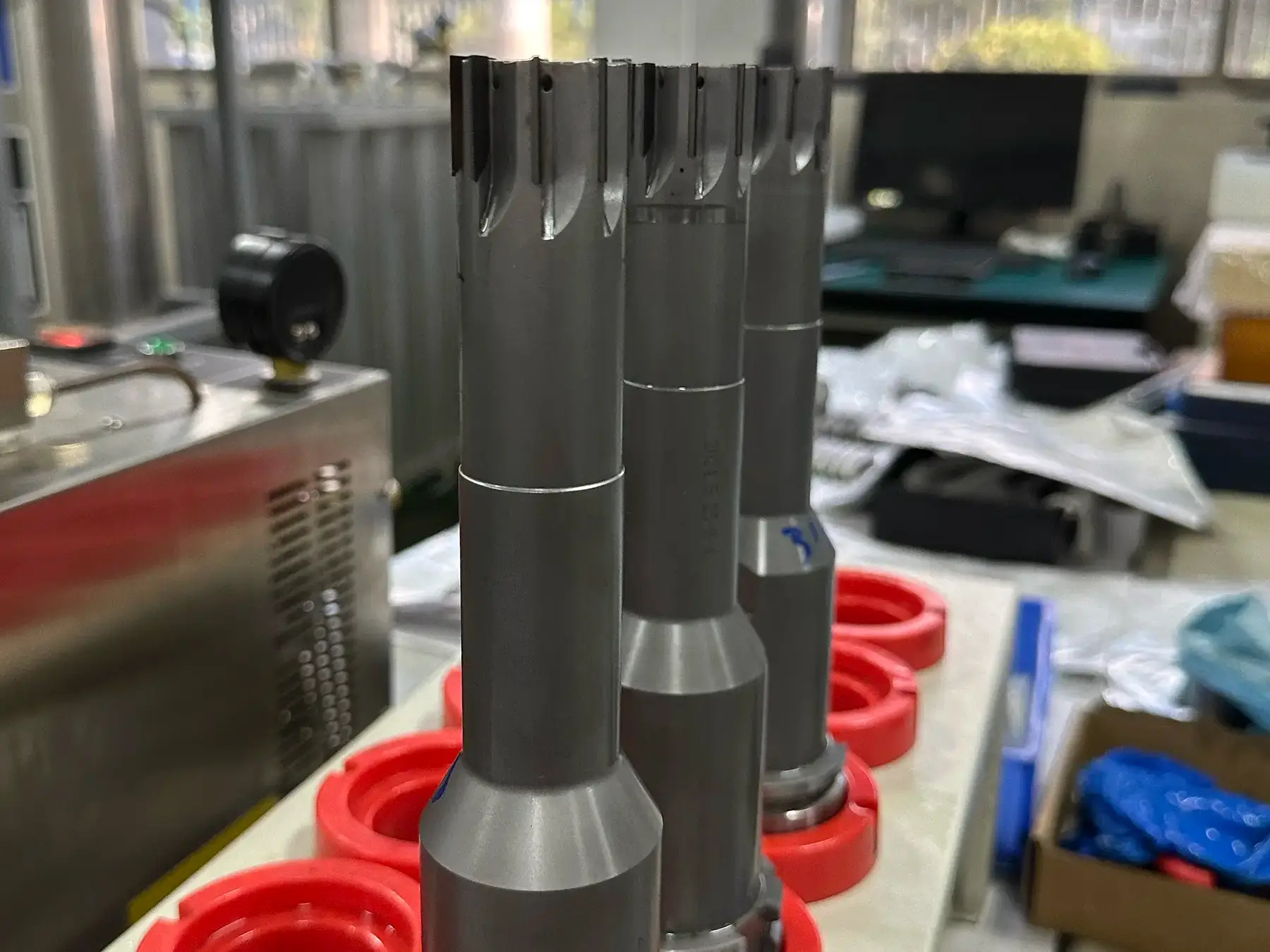
O alargamento PCD é um acabamento de furos: a rotação calculada é apenas uma parte de obter dimensão e acabamento. Para alargadores PCD, a fonte disponível identifica qualidade do material, teor de silício, diâmetro, tolerância, refrigeração, evacuação, rigidez da máquina, conceção e acabamento pretendido como condições que afetam a velocidade. Fatores da velocidade de corte dos alargadores PCD
Confirmar as condições antes de introduzir velocidade ou avanço
A pergunta útil não é apenas «Que RPM usar?», mas «Esta velocidade periférica ou avanço por rotação aplica-se a este furo e preparação?». Reúna os dados seguintes antes de tratar um comando calculado como ajuste de processo.
| Grupo de dados | Confirmar antes de calcular | Por que altera a decisão |
|---|---|---|
| Material da peça | Qualidade e, quando relevante, teor de silício | São variáveis citadas para decidir o alargamento PCD. |
| Furo e ferramenta | Diâmetro do alargador, conceção, estado do furo, tolerância e acabamento pretendido | O diâmetro entra na conversão para RPM; os restantes requisitos determinam se o dado escolhido é aplicável. |
| Máquina e processo | Rigidez, refrigeração e evacuação de aparas | Estas condições podem determinar se um ajuste nominal é estável na operação real. |
| Dados validados | Velocidade periférica e avanço por rotação do fabricante ou de um processo interno validado | Este artigo converte o dado; não cria um valor inicial PCD. |
A distinção importa sobretudo com tolerâncias apertadas. Introduzir um diâmetro na fórmula não prova que a velocidade sirva para material, ferramenta e preparação.
Converter uma velocidade periférica validada em RPM
Em polegadas, calcule a rotação com:
Símbolos em polegadas: n = velocidade do veio em rpm; Vc = velocidade periférica validada em ft/min (SFM); e D = diâmetro do alargador em polegadas. Use esta conversão apenas quando Vc estiver validada para o alargador PCD, material, furo e preparação exatos. Não são dados de corte PCD.
A fórmula converte uma velocidade periférica já escolhida; não a seleciona. Um diâmetro maior produz menos RPM com os mesmos SFM validados; alterar o diâmetro mantendo as RPM altera a velocidade da aresta.
Cálculo genérico de alargamento de alumínio: não são dados de corte PCD. Uma fonte genérica de alargamento usa Vc = 300 SFM e D = 0.500 in.
É uma ilustração reproduzível da fórmula de um exemplo genérico de alargamento de alumínio. São dados alheios ao corte com PCD e não devem ser usados como recomendação de velocidade inicial PCD. Fonte e exemplo
Se a recomendação PCD validada usar outro sistema de unidades, obtenha o método correspondente do fabricante ou documentação validada. As evidências aceites aqui sustentam a relação em polegadas acima, não uma nova derivação métrica.
Converter avanço por rotação em avanço linear apenas se a definição corresponder
O avanço linear acompanha a rotação apenas se o dado de avanço estiver definido por rotação:
Símbolos: F = avanço linear em in/min; n = rotação do veio em rev/min; e frev = avanço validado em in/rev. Aplicar apenas se for definido por rotação para o alargador PCD e a operação exatos. Não são dados de corte PCD.
Não substitua o dado por avanço por dente salvo se a documentação definir a relação com o avanço por rotação para esse alargador. As evidências aceites não fornecem o número de dentes nem a definição necessários para essa conversão.
Cálculo genérico de avanço em alumínio: não são dados de corte PCD. A mesma fonte genérica indica 0.004 in/rev como avanço base de furação e calcula:
Resultado: 9.2 IPM. A fonte aplica depois um multiplicador de alargamento específico. Nem 0.004 in/rev nem esse multiplicador são dados de alargador PCD. Este cálculo fornece dados alheios ao corte com PCD e não deve ser usado como recomendação de avanço PCD. Fonte e exemplo
O fluxo seguro é obter velocidade periférica PCD e avanço por rotação PCD validados, calcular RPM e avanço linear, confirmar unidades e registar as condições que tornam esses dados válidos.
Calculadora de RPM e avanço de alargadores PCD
Introduza velocidade periférica e avanço por rotação apenas após validar ambos para o alargador PCD, material, furo e preparação exatos. A calculadora converte-os em RPM e avanço linear; não cria dados de corte PCD.
Apenas dados validados. O resultado não valida velocidade ou avanço por rotação para outra ferramenta, liga, tolerância, acabamento ou preparação.
Rever o cálculo validado quando a operação mudar
Guarde juntos o dado escolhido e o cálculo. Conserve pelo menos material e liga, diâmetro e conceção do alargador, estado do furo, tolerância e acabamento, porta-ferramentas/preparação, refrigeração e evacuação, fonte validada de velocidade/avanço por rotação e comandos RPM/avanço resultantes. Não comprova a transferência para outra operação; permite rever o ajuste quando a mesma operação muda.
Se o resultado não for aceitável, evite alterar várias variáveis ao mesmo tempo. Identifique que condição mudou ou que ramo de diagnóstico tem evidências. O cálculo pode estar correto embora o dado já não seja aplicável por alterações de material, furo, rigidez ou controlo de aparas. A fonte PCD inclui essas condições na decisão; a calculadora genérica explica que as RPM convertem velocidade periférica e diâmetro. Registe condições antes/depois e inspeção para distinguir alteração de preparação de erro de cálculo. Variáveis de decisão PCD Fonte genérica da fórmula de alargamento
Se um limite da máquina exigir outras RPM, não suponha que a velocidade PCD original continue válida nem que o avanço deva manter-se. Consulte a discrepância com o fabricante ou responsável pelo processo validado para validar a nova condição. É um limite de decisão, não uma regra alternativa de parâmetros.
Diagnosticar o furo antes de alterar apenas a velocidade
Desvio dimensional, mau acabamento, rebarbas e vibrações não provam que apenas as RPM estejam erradas. A fonte PCD aceite pede evidências diferentes conforme o sintoma: tolerância, material, refrigeração, estado da ferramenta e dados atuais. Use o sintoma para escolher o primeiro controlo.
| Sintoma | Evidências a recolher primeiro | Possíveis causas a distinguir | Limite da ação corretiva |
|---|---|---|---|
| Desvio dimensional do furo | Dimensão/tolerância real, vida da ferramenta e problema de inspeção | Desgaste do alargador, rigidez, evacuação, refrigeração, geometria e comportamento do material | Corrigir a causa confirmada e rever a dimensão antes de alterar um comando calculado. |
| Mau acabamento superficial | Acabamento pretendido, estado ou fotografia do furo, material e refrigeração | Estado da ferramenta, rigidez da preparação, evacuação, contexto de avanço/velocidade e comportamento do material | Comparar evidências equivalentes e alterar uma variável controlada de cada vez. |
| Rebarbas ou vibrações | Estado da rebarba/furo/ferramenta, dados de corte atuais e contexto de máquina/preparação | Geometria, estado da aresta, evacuação, velocidade/avanço, comportamento do material e balanço/rigidez | Restabelecer a condição identificada de preparação ou processo antes de indicar uma alteração de velocidade. |
A fonte sustenta um fluxo de recolha de diagnóstico, não um mapa de um sintoma por causa. Por exemplo, vibrações devem levar a verificar rigidez, balanço, ferramenta, refrigeração e evacuação com os valores programados, não a reduzir automaticamente as RPM. Dados de problemas de alargador PCD
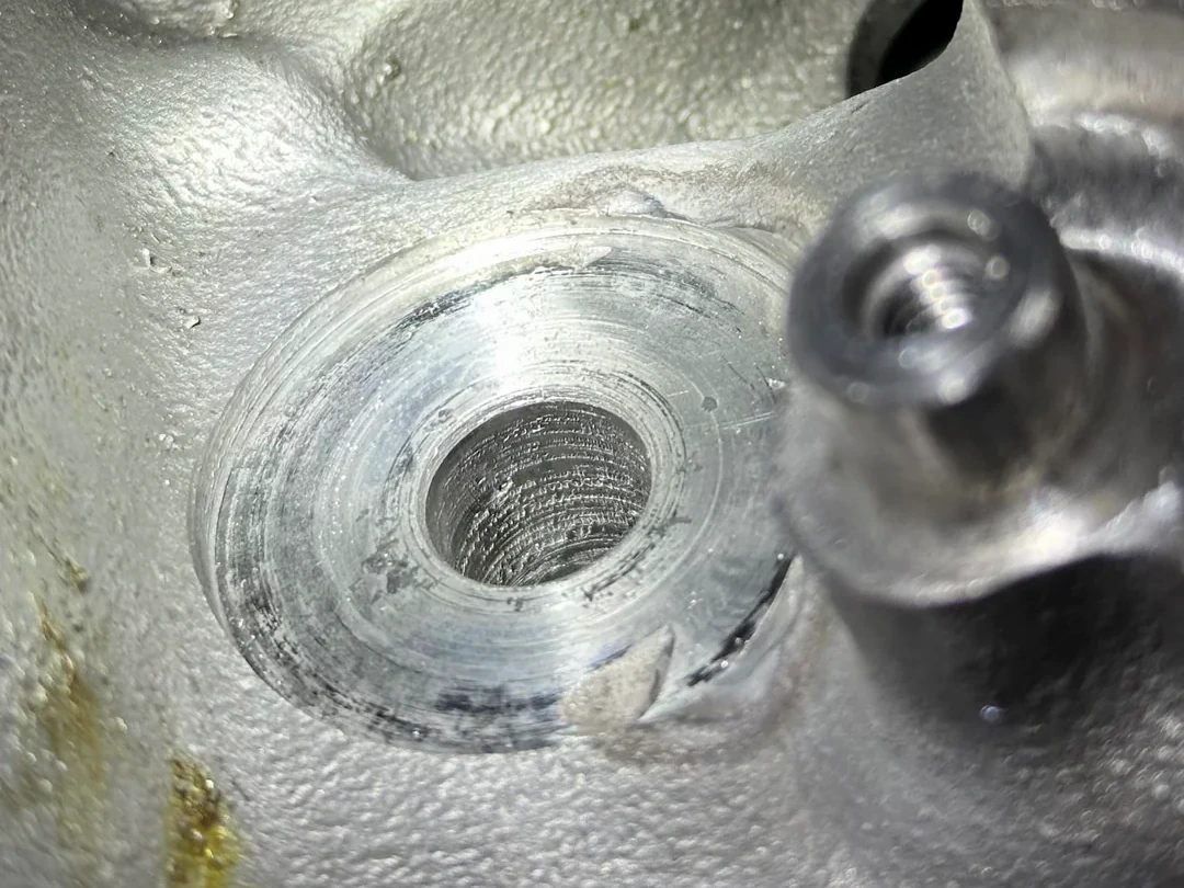
Um caso real em alumínio mostra por que conservar o contexto
Um fórum descreve um problema de alargamento CNC de alumínio com alargador de 0.0624 in após pré-furo de 0.052 in, entrada alargada em boca, balanço e dúvidas sobre ciclos G85/G81. As respostas discutiam aumentar o pré-furo, reduzir ajustes de ensaio, encurtar o balanço e mudar o ciclo. É um caso autêntico único, não evidência PCD, padrão recorrente ou consenso setorial. A utilidade limitada é mostrar por que pré-furo, balanço e ciclo devem acompanhar qualquer discussão de velocidade/avanço. Caso de fórum
Separar o cálculo da seleção
Use as fórmulas para converter dados validados, não para preencher um parâmetro PCD ausente. Se o resultado não cumprir tolerância, acabamento ou estabilidade, conserve material, diâmetro, objetivo de qualidade, rigidez, refrigeração, evacuação e estado da ferramenta durante a investigação. Acrescente fonte validada e inspeção. Assim, a alteração seguinte será testável e verificável.
Para aceder a famílias candidatas, consulte a gama de alargadores PCD. Esta ligação serve apenas para navegar; não comprova material compatível, tolerância, geometria, disponibilidade ou desempenho.