


Escariadores helicoidales o rectos: elegir según dirección de viruta y agujero
Al elegir un escariador helicoidal o recto , elija según el problema que deba resolver el canal. Un escariador recto sigue siendo adecuado para muchos agujeros continuos, bien preparados y con evacuación controlada. Uno helicoidal resulta útil si el sentido de hélice verificado mejora el movimiento de viruta, suaviza el contacto en interrupciones o favorece el acabado y las rebabas requeridos.
No pida solo por las palabras «recto» o «helicoidal». Importan sentido de corte, sentido de hélice, tipo de agujero, destino de viruta, material, interrupción, entrada y datos del proveedor. La hélice no es automáticamente una mejora ni el canal recto una herramienta poco precisa.
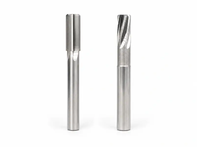
Empezar por nombrar correctamente la geometría
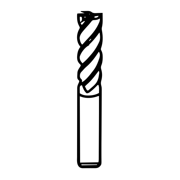
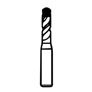
Un canal recto discurre casi paralelo al eje; uno helicoidal lo rodea en espiral. Eso cambia la entrada del filo y puede influir axialmente en la viruta, pero no describe toda la herramienta.
El sentido de corte indica qué giro produce el corte. El sentido de hélice describe la dirección de la hélice. Un escariador puede cortar a derechas con hélice a izquierdas, por ejemplo. Confundir los términos puede invertir la dirección esperada de viruta o hacer pedir una herramienta incorrecta.
Las convenciones del catálogo ayudan, pero mandan el plano exacto y las indicaciones del fabricante. Verifique:
- el giro de corte;
- la hélice a izquierdas o derechas;
- la dirección prevista de viruta;
- la aptitud para agujeros pasantes, ciegos o interrumpidos;
- la geometría de entrada y corte frontal;
- el recorrido del refrigerante y la retirada recomendada;
- si es un escariador manual, de sujeción en portaherramientas, de máquina, ajustable o especial.
No deduzca el flujo de una foto. Pida al proveedor confirmar adónde deben ir las virutas con el giro real de corte.
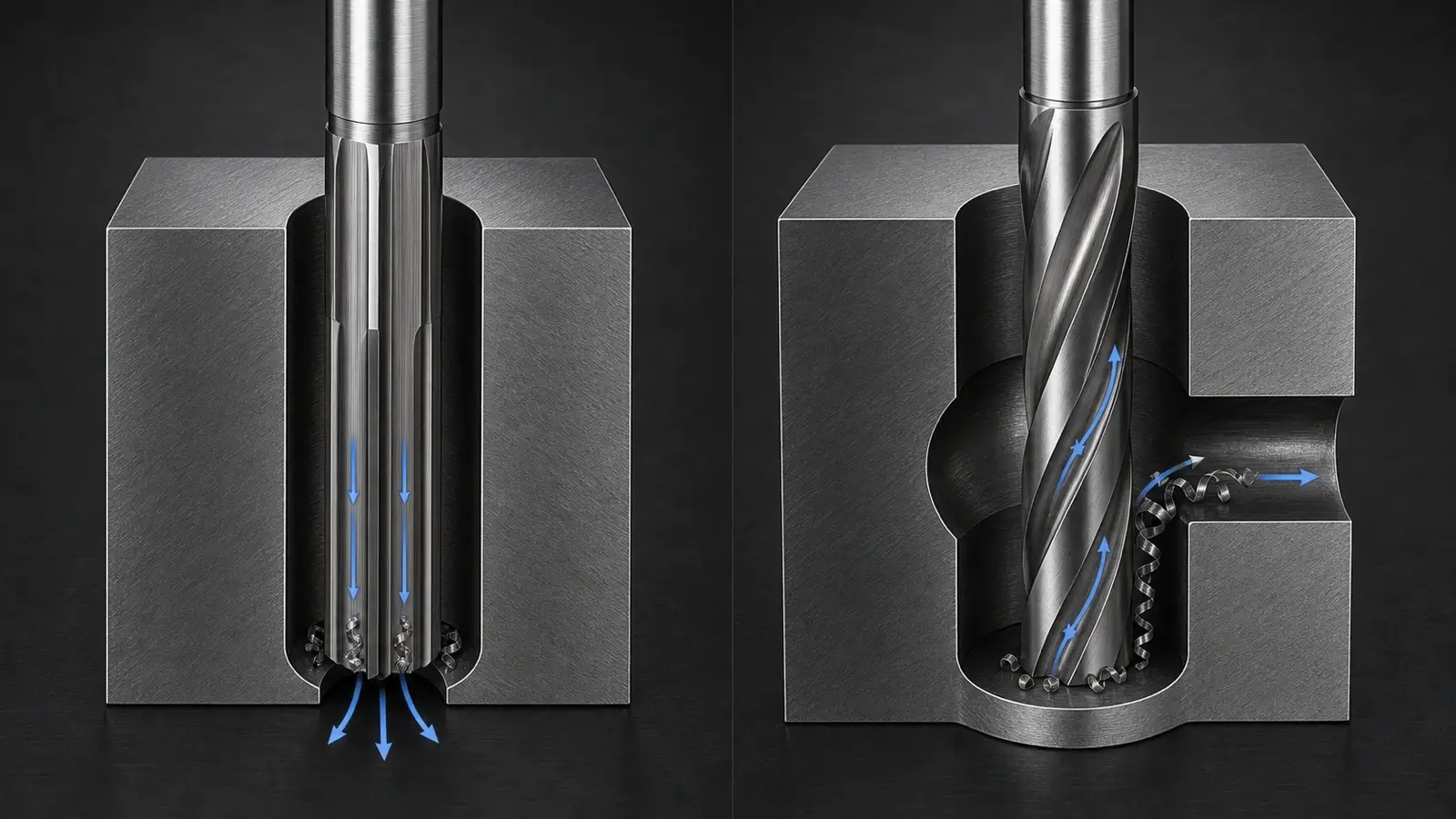
Qué hacen bien los canales rectos
Un escariador de canales rectos ofrece espacios axiales sin efecto helicoidal de transporte. En un agujero continuo con salida suficiente o volumen de viruta controlado, esa simplicidad puede ser ventajosa. La geometría es conocida, disponible y precisa si son correctos agujero previo, sobrematerial, alineación, descentramiento, datos de corte, lubricación y filos.
El canal recto es una base válida, no un recurso inferior. Si un proceso estable cumple medida, geometría, acabado, vida y control de viruta, cambiarlo porque la hélice parece más sofisticada añade coste y variables sin beneficio definido.
Los límites aparecen cuando hace falta la acción de la hélice. Los filos rectos encuentran más bruscamente agujeros transversales, chaveteros o interrupciones. Las virutas pueden carecer de dirección axial preferente si gravedad, refrigerante y geometría no las evacuan. Un agujero ciego puede atraparlas en el fondo; uno profundo agrava recorte y acceso del fluido. Son límites de aplicación, no prueba de fallo universal.
Qué cambian los canales helicoidales
Un escariador de canales helicoidales escalona el contacto a lo largo de la hélice. En vez de que un filo recto encuentre la interrupción en la misma posición axial, el contacto puede avanzar por el canal. Esto puede reducir impactos y mantener soporte alrededor de agujeros transversales, chaveteros u otras interrupciones.
La hélice influye también en la dirección axial. En configuraciones habituales de corte a derechas, una hélice izquierda verificada puede empujar la viruta hacia delante y una derecha atraerla hacia el mango. Trátelo como hipótesis hasta confirmación del fabricante exacto. Entrada, canal, refrigerante y material pueden alterar el comportamiento real.
La hélice también implica compromisos. Fuerzas axiales y movimiento de viruta deben ajustarse al agujero y montaje. Una herramienta que lleva viruta a la entrada puede ayudar en un ciego, pero producir carga o acabado distintos de otra que la empuje a través. Un mejor acabado atribuido a una hélice no se transfiere automáticamente entre familias, materiales y sobremateriales.
No confunda influencia axial con garantía de evacuación de virutas. El escariado debe producir viruta controlada y relativamente pequeña, pero un material dúctil puede formar hilos o adherirse. Suministro de refrigerante, volumen de canal, profundidad, entrada y retirada determinan la salida real. La hélice favorece una dirección; no despeja sola una salida bloqueada o un canal lleno.
Los profesionales experimentados describen la hélice como solución a problemas, especialmente interrupciones y dirección de viruta, y señalan que los canales rectos funcionan bien cuando esos problemas no existen. Esa frontera condicionada es más útil que una clasificación universal.
Elegir según el destino de la viruta
Agujeros pasantes
Un agujero pasante ofrece salida tras la longitud acabada si hay espacio para la entrada del escariador y las virutas. Una geometría verificada por el fabricante que empuje hacia delante puede alejar las virutas de la pared acabada y sacarlas por la salida.
Compruebe qué hay detrás: superficie de sujeción, hombro, forma próxima o salida insuficiente pueden bloquear el recorrido. Confirme que el fluido llega al corte y que no se acumulan virutas entre escariador y salida. El canal recto sigue siendo eficaz con viruta pequeña, salida abierta y evacuación controlada.
Prevea espacio axial para que la entrada rebase toda la superficie a diámetro completo antes de retirar. Si el escariador invierte o retrocede mientras la entrada cortante permanece en la longitud especificada, las marcas pueden atribuirse erróneamente al canal. Incluya espacio de salida y retirada en el plan de prueba.
Agujeros ciegos
Un agujero ciego tiene espacio de fondo limitado y no tiene salida frontal. Empujar virutas delante puede compactarlas bajo la entrada, rayar la pared o impedir alcanzar profundidad. Una hélice confirmada que las lleve a la entrada puede ser preferible si el material exige evacuación activa.
Para la evacuación de virutas en agujeros ciegos, compare el volumen útil del canal con el sobrematerial y profundidad previstos y verifique si la refrigeración interna u otro suministro apoya el recorrido. Elevar viruta axialmente solo ayuda mientras el canal siga abierto.
La geometría del fondo sigue siendo crítica. Punta taladrada, exigencia de fondo plano, longitud de entrada, longitud útil, profundidad y volumen de viruta deben ser compatibles. Una hélice ascendente no compensa una entrada que impida alcanzar el diámetro completo antes del fondo. Confirme la retirada y evite arrastrar virutas atrapadas por la pared acabada.
Agujeros interrumpidos, transversales y chaveteros
Un agujero interrumpido retira repetidamente el soporte a los filos. Agujeros transversales, ranuras y chaveteros pueden crear impactos, astillado, vibración, rebabas y cambios locales de medida. El contacto helicoidal supera la interrupción progresivamente y mantiene contacto mientras otra sección cruza el hueco.
Describa la interrupción, no escriba solo «interrumpido». Registre ancho, profundidad, orientación, posición axial, estado de bordes y relación con el diámetro. Un pequeño agujero transversal y un chavetero interno ancho no eliminan el mismo soporte. Verifique hélice, material de corte y entrada para esa forma.
Si un canal recto ya cruza la interrupción sin carga, acabado o daño inaceptables, quizá no haga falta cambiar. Si marcas de impacto o astillado recurrente coinciden con la interrupción, la hélice se convierte en una prueba fundamentada, no estética.
No elegir el canal solo por el nombre del material
El material afecta forma de viruta, adhesión, abrasión, fuerza y requisitos del filo. Uno frágil de viruta corta difiere de uno dúctil de viruta continua o adhesiva. Tratamiento, piel de fundición, inclusiones, aporte de soldadura y zonas afectadas térmicamente pueden hacer variar una misma aleación dentro del agujero.
Esa variabilidad impide una regla simple «recto para A, helicoidal para B». La herramienta debe combinar material de corte, agudeza, desprendimiento, entrada, margen, recubrimiento o pulido, espacio y refrigeración adecuados. El sentido de hélice es solo un elemento.
Un caso revisado de un agujero de aluminio reparado por soldadura ilustra ese límite. La medida era correcta pero la superficie parecía desgarrada y grandes cambios de velocidad no ayudaron. La discusión pasó a aporte, agudeza, lubricación, calidad del escariador y acabado alternativo. No demuestra un canal preferible; muestra que material y filo pueden dominar la elección recto/helicoidal.
Separar problemas de medida y acabado del tipo de canal
Si medida o aspecto son malos, conserve el montaje fallido antes de pedir otro canal. Mida por profundidad y orientación; compare agujero previo, sobrematerial, chaflán y eje. Compruebe descentramiento del conjunto e inspeccione entrada, márgenes y filos buscando desgaste, astillado y material adherido.
Verifique fluido en la entrada, virutas, datos de corte, pausa y retirada. Una helicoidal con sobrematerial incorrecto, filo dañado o descentramiento excesivo puede ir peor que una recta controlada. Una recta bien preparada puede superar una helicoidal elegida de una tabla genérica.
Defina también «mejor acabado». Brillo, rugosidad medida, características de meseta y estanqueidad son requisitos distintos. En una discusión revisada por una persona, el diagnóstico pasó de velocidad y avance a descentramiento, sobrematerial, lubricación, estado del escariador, estabilidad del mandrinado y adecuación del bruñido a una superficie de sellado hidráulico. El canal solo no resolvía la función.
Clasifique el fallo antes de cambiar la geometría:
- todo el agujero sobremedida: comprobar medición, diámetro de herramienta, descentramiento, alineación y filos;
- entrada acampanada o marcada: comprobar aproximación, chaflán, contacto de entrada y pausa;
- conicidad o acabado variable con profundidad: comparar agujero previo, acumulación de viruta, acceso de fluido y flexión;
- rayas: inspeccionar virutas recortadas, retirada y márgenes dañados;
- fallo en interrupción: examinar punto de impacto, soporte restante y rebabas.
Cambie a helicoidal o recto solo si la evidencia identifica un mecanismo sobre el que influya la geometría.
Definir los datos antes de solicitar una herramienta
Facilite diámetro acabado y tolerancia, profundidad y condición pasante/ciega, espacio de fondo, cada agujero transversal o ranura, material y estado, agujero previo y sobrematerial, acabado, máquina/husillo, portaherramientas y capacidad de descentramiento, fluido, volumen de producción y fallo observado si sustituye.
Solicite después confirmación de sentidos de corte y hélice, dirección de viruta, entrada, canal, material de corte, tolerancia, longitud útil, recorrido del fluido y datos de aplicación.
La gama de escariadores de PCD permite identificar familias PCD candidatas tras definir esos datos. No verifica sentido de hélice, dimensiones, disponibilidad ni adecuación al material de una familia. Confirme plano elegido y datos de aplicación antes de programar.
Validar la elección en un agujero de prueba controlado
Haga un agujero de prueba con material, agujero previo, sobrematerial, máquina, portaherramientas, fluido y ciclo previstos. Registre datos reales y ajustes de velocidad/avance. Documente destino de virutas y restos en canal, fondo o pared acabada.
Mida diámetro en entrada, centro y salida o fondo, en varias orientaciones si procede. Inspeccione conicidad, abocardado, redondez, rebabas, acabado y marcas en interrupciones. Registre carga del husillo, sonido y estado de filos.
Al comparar recto y helicoidal, cambie solo el sistema de herramienta y los datos necesarios para cada geometría aprobada. Mantenga el plan de calidad. Gana la herramienta que produce agujeros aceptables repetibles con control sostenible de viruta y filos, no la de canal más complejo.
Conclusión
Un canal recto basta si un agujero continuo bien preparado ofrece control estable de viruta y cumple medida, acabado y vida. La hélice se elige cuando un sentido verificado o contacto progresivo resuelve un problema concreto de agujero pasante, ciego o interrumpido.
Elija siguiendo la viruta, definiendo la forma y confirmando el plano exacto. Valide después el proceso completo; el tipo de canal nunca es la especificación del agujero terminado.