



2-Flute vs 4-Flute End Mill: Choose by Chip Space, Rigidity, and Cut
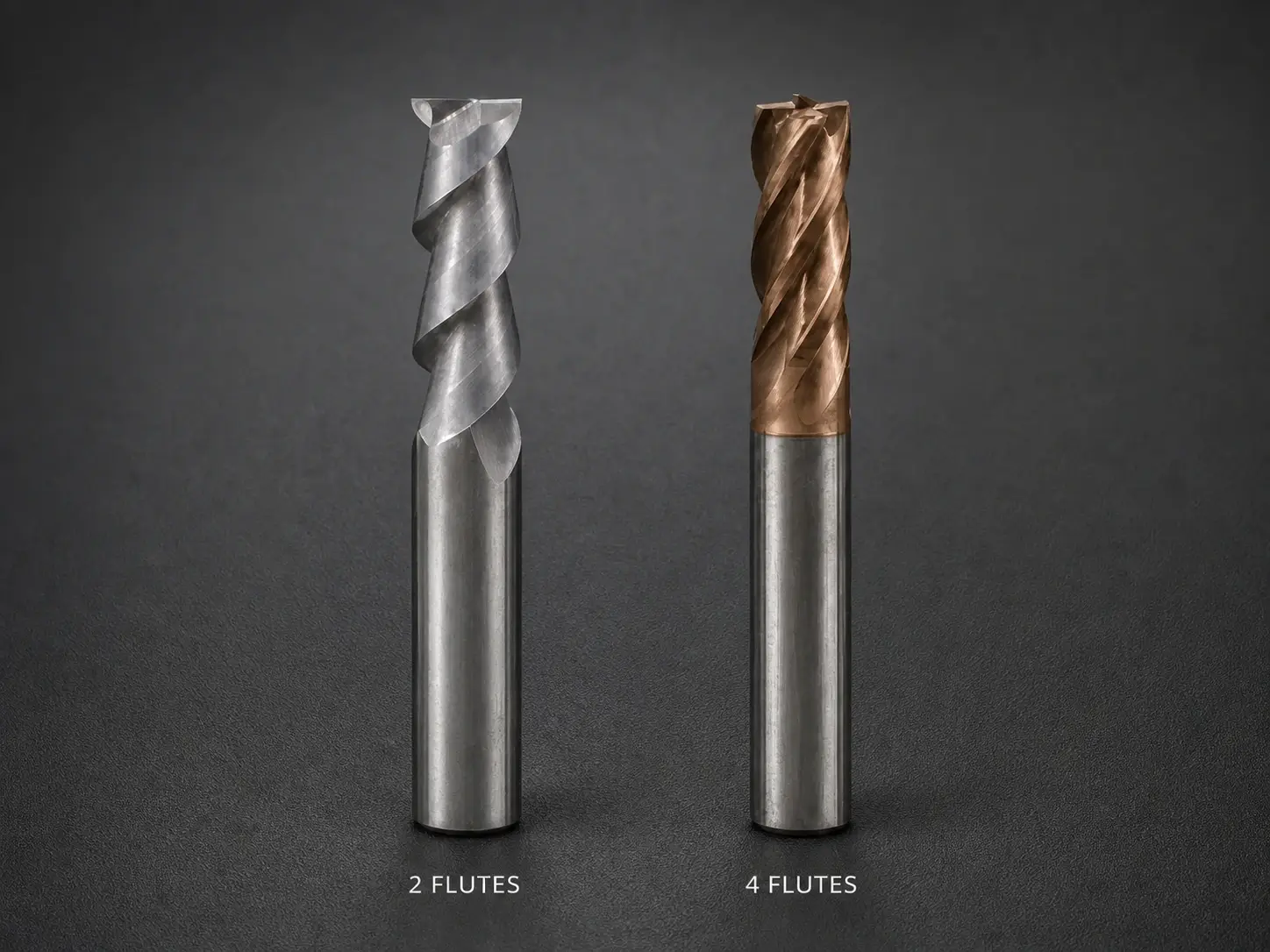
Choose a 2-flute end mill when chip space and evacuation are the first constraints. Choose a 4-flute end mill when the exact tool’s section and added edge frequency suit the cut, and the machine can supply the required table feed without trapping chips. Those are starting directions, not material rules.
The useful comparison is not simply “aluminum versus steel.” Full slotting in steel may need more chip space than a light side-finishing pass in aluminum. A sharp, polished 4-flute design can behave differently from a general-purpose 4-flute tool, just as two 2-flute cutters can have different cores, helix angles and edge preparations. Compare the actual tools under one defined operation.
The quick choice
Start with the cut, then the material.
The 2-flute candidate deserves the first look when chips are large, stringy, adhesive or difficult to remove; when the cutter is buried in a slot; when the machine has limited feed capability at high spindle speed; or when a small diameter leaves very little flute volume.
The 4-flute candidate deserves the first look when engagement is open or controlled, chips have a reliable exit, the matched tool family uses the extra flutes to provide a useful section or edge frequency, and the machine can maintain the specified feed per tooth. It may also be attractive for finishing, but “four flutes equals better finish” is not a rule. Runout, tooth loading, edge condition and vibration can defeat that expectation.
The search phrase 2 flute vs 4 flute end mill names the comparison but omits its conditions. Add material and hardness, operation, radial and axial engagement, diameter, reach, machine limits, holder/runout, evacuation and the drawing requirement before making the choice.
If both candidates pass that first screen, compare the constraint that production actually pays for. A roughing operation may value reliable chip removal and edge life more than a small cycle-time difference. A finishing operation may value wall form and a stable surface more than theoretical material-removal rate. On a short run, using the qualified tool already in the crib may be sensible; on repeated production, a controlled A/B proof can justify a dedicated purchase. The decision metric should be named before the test so the operator does not select whichever cut merely sounds quieter.
Compare chip space before counting edges
At the same nominal diameter, two flutes usually leave more circumferential room for each flute gullet than four. That extra chip space can help a cutter accept and transport larger chips. Four flutes put more cutting edges and flute channels around the same circumference, so each channel may have less volume.
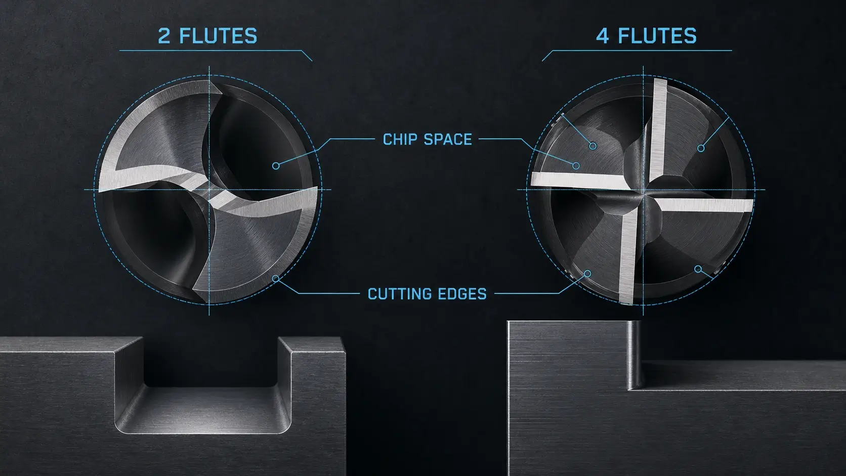
“Usually” matters. Manufacturers can alter core diameter, flute depth, rake, helix and unequal spacing. A purpose-designed 4-flute aluminum tool may have a very different gullet from a compact general-purpose tool. Flute count is visible, but the sectional drawing and application data tell you how space was actually allocated.
Chip demand comes from the operation. Full slotting surrounds both sides of the cutter and restricts chip escape. Deep axial engagement asks chips to travel farther through the flutes. Pocket corners can increase engagement suddenly. By contrast, a light side cut leaves an open side and may produce a smaller chip volume per revolution.
Material changes the chip as well. Some aluminum conditions and plastics can produce long, adhesive or bulky chips. If those chips remain near the edge, they can be cut again, smear onto the flute or raise heat. Sharp geometry and a generous gullet may therefore matter more than adding cutting edges. The reviewed Delrin discussion in the evidence package illustrates the point: users disagreed widely on speed and coolant, but repeatedly returned to sharp geometry, adequate tooth load and chip clearance. Their numeric settings are not transferable.
Steels can form shorter or more manageable chips under some conditions, which may allow four flutes to work effectively. But a deep full slot in steel is still a restricted chip path. Do not use the material name to ignore engagement and evacuation.
Judge the result at the cutter. Chips should leave the flute without packing or being repeatedly crushed. Built-up material, discolored or powdery chips, scratches from recutting and rising load are evidence that the selected geometry or process is not clearing the cut.
Four flutes change the command as well as the cutter
Flute count appears directly in the table-feed calculation:
Table feed = RPM × flute count × feed per tooth
At the same RPM and feed per tooth, a 4-flute cutter requires twice the table feed of a 2-flute cutter. That does not mean it always removes material twice as fast. Engagement, depth, cutter data, machine power and chip evacuation still limit the operation. It does mean that changing count without recalculating feed changes tooth loading.
Suppose a machine can reach the required spindle speed but not the table feed commanded for four flutes. If the programmer caps feed while leaving RPM unchanged, actual feed per tooth falls. The edge may take a thinner chip, rub more or fail to reach the cutting condition assumed by the tool data. The better response may be to lower RPM and recalculate table feed, choose another cutter or change the operation. A feed ceiling is a selection input.
The reverse mistake is also possible. Replacing a 4-flute tool with two flutes while preserving the same table feed and RPM doubles the calculated feed per tooth. That can overload the edge even though the tool has more chip space.
Tooth-passing frequency also changes. Four edges contact the work more often per revolution than two. In a stable finishing cut, that edge frequency may help produce more closely spaced feed marks at a given table feed. In an unstable system, it can excite a different vibration response. Flute count does not guarantee smoothness; it changes one excitation input.
Machine acceleration and short toolpaths matter too. A programmed feed may never be reached in small pockets or around tight direction changes. Compare the achieved feed and engagement, not only the CAM value. The control, path and machine dynamics decide whether the four-flute feed advantage exists in the cut.
Compare strength and deflection by drawing, not folklore
Four-flute end mills are often described as stronger because a designer can use a larger core when each flute removes less circumferential material. Two-flute tools are often described as weaker because deeper gullets remove more section. These tendencies can be useful, but flute count alone does not establish core diameter, neck size or bending stiffness.
Compare model drawings or verified tool data. Look at core and web design, flute depth, cutting length, reduced neck, overall reach, shank, helix and edge preparation. A stout 2-flute tool with short flute length can be more rigid in an assembly than a long-reach 4-flute tool. A specialized 4-flute cutter may intentionally trade some core for chip space.
Tool stickout can overwhelm the difference. Bending sensitivity rises rapidly as the cutting edge moves farther from the holder. If two candidate tools require different gauge lengths or flute lengths, their flute count is no longer the only changing variable. Holder condition, runout, workpiece support and cutting force also affect deflection.
More cutting edges do not automatically share the load equally. Runout can put one tooth farther from the rotational center, so that tooth removes more material. With four flutes, the extra edges cannot compensate for a holder or collet that makes one edge dominate. Measure runout at a relevant location and inspect all cutting edges after the proof cut.
The correct strength question is not “Are four flutes stronger?” It is “Which exact assembly has enough section and edge support for this engagement and reach while still leaving enough chip space?”
Let the operation reverse the material shortcut
Material narrows the candidates, but the operation can reverse the first choice.
When two flutes become the safer candidate
Two flutes move ahead when the cut generates more chip than the available flute channels and evacuation system can remove. Common reasons include full slotting, deep axial contact, small cutter diameter, sticky or stringy chips and limited coolant or air access.
They can also fit machines that run high spindle speeds but have modest feed limits. With two teeth, the table feed needed to maintain a specified feed per tooth is lower than it is with four at the same RPM. This can help a router or light machine stay within its feed envelope. The tool still needs appropriate geometry and cutting data; fewer flutes do not cure weak workholding or a poor spindle.
Plastics and aluminum often send the selection in this direction because sharp edges and chip volume matter. Yet an open finishing pass with effective evacuation may accept a well-designed 4-flute tool. The operation must confirm the choice.
When four flutes become the better candidate
Four flutes move ahead when chip evacuation is already controlled and the application can use more edge contacts, a matched core/section or higher potential feed. Open side milling, controlled radial engagement and finishing are common candidates because the chip has an exit and the cutter is not buried across its diameter.
Some steel operations fit this condition, especially with a cutter designed for the material and engagement. The four-flute tool may provide the required edge support and productivity without overfilling its gullets. But if the machine cannot reach the calculated table feed, or if a deep slot traps chips, the nominal advantage disappears.
A finish requirement can favor four flutes only after runout, vibration and edge condition are under control. Four unevenly loaded edges can leave a worse surface than two correctly loaded edges.
When neither count fixes the operation
Do not choose between two and four until the process itself is credible. Excessive tool stickout, damaged collets, poor runout, a flexible wall, packed chips, unsuitable entry, abrupt engagement or a machine resonance can break either cutter.
The operation may need a shorter assembly, staged depth, different path, better evacuation, stronger workholding or another tool family. A 3-flute or application-specific high-flute cutter may eventually be the right answer, but that belongs to a broader flute-count selection. For this comparison, “neither” is a valid decision when the physical constraint is outside flute count.
Do not blame flute count for an assembly problem
A reviewed shop case in the evidence package involved repeated breakage of a small 4-flute end mill during slotting in prehardened steel. The discussion did not isolate four flutes as the root cause. It exposed substantial runout, long reach, full-slot engagement, holder/collet condition and a legacy program. Those variables created uneven tooth loading and deflection that a flute-count label could not explain.
Use that diagnostic order when a tool fails:
- verify the installed cutter and actual operation match the selected data;
- measure runout and inspect holder, collet, taper and clamping condition;
- confirm tool stickout, cutting length, holder clearance and work support;
- review radial and axial engagement, entry and chip exit;
- calculate actual feed per tooth from achieved RPM and table feed;
- inspect every edge and the chips before changing count.
If one flute shows most of the damage, investigate runout or local edge damage. If all gullets are packed, investigate chip volume, flute architecture and evacuation. If the surface and load change only at certain path directions, investigate engagement and machine dynamics. These observations discriminate among causes better than “the four-flute cutter broke.”
The high-flute evidence case reaches the same boundary from another direction. A specialized multi-flute cutter experienced chatter until chip delivery and evacuation improved, after which workholding became the next limit. More edges did not remove the need to verify the rest of the system.
Compare actual tools, not flute-count labels
Select two real item numbers. Confirm diameter, flute count, cutting length, reach, core or neck information where available, helix, rake and edge preparation, substrate, coating, center-cutting capability and approved materials and operations. Compare cutting data under the same engagement definition.
For the matched-model comparison, browse the carbide end mill to identify candidate families. It is not proof that a listed 2-flute or 4-flute tool has a particular core, polished flute, coating, slotting capability or performance level. Use the exact model drawing and application data.
Keep dissimilar geometry visible in the decision. If the 2-flute candidate is polished and uncoated while the 4-flute candidate has a honed edge and a steel-oriented coating, the test is not flute count alone. That may be the practical purchasing choice, but document the complete tool identity rather than attributing the result to two versus four.
Ask for application support when the tool data does not cover the material condition, engagement, reach or machine. Do not fill the gap with a universal material chart.
Make the choice with five checks
First, check the chip path. If the cut is enclosed, deep, sticky or difficult to flush, favor the candidate with verified chip space and evacuation. That is often the 2-flute tool, but geometry can change the result.
Second, check the required command. Calculate table feed for each tool at its own approved RPM and feed per tooth. Confirm the machine can achieve both without turning the cut into rubbing or overload.
Third, check stiffness and reach. Compare the actual assemblies, not nominal flute counts. Minimize stickout, verify holder clearance and measure runout.
Fourth, check operation and material together. Full slotting, roughing, controlled-engagement side cutting and finishing impose different chip and force conditions even in the same material.
Fifth, prove the selected tool. Record the assembly and commands, observe load and sound, inspect chip shape and evacuation, measure the feature and finish, and inspect every edge. Change only one variable before the next proof.
Choose two flutes when the measured constraint is chip room or attainable tooth loading. Choose four when chip clearance is secure and the exact four-flute design provides a useful section, edge frequency or feed opportunity that the machine can use. If runout, reach, engagement or evacuation is unresolved, correct that problem before calling either flute count the winner.