



Chip Thinning in Milling: How to Correct Feed for Radial Engagement
In chip thinning milling, reducing radial engagement can make the chip seen by the cutting edge thinner than the programmed feed per tooth suggests. That sounds harmless, but an edge that is asked to take too little material may spend more time rubbing, generating heat and wearing than cutting cleanly. The correction is not “always feed faster.” It is to determine whether radial chip thinning is active, calculate from the target maximum chip thickness for the exact tool, and prove the result under the real machine conditions.
First decide whether radial chip thinning applies
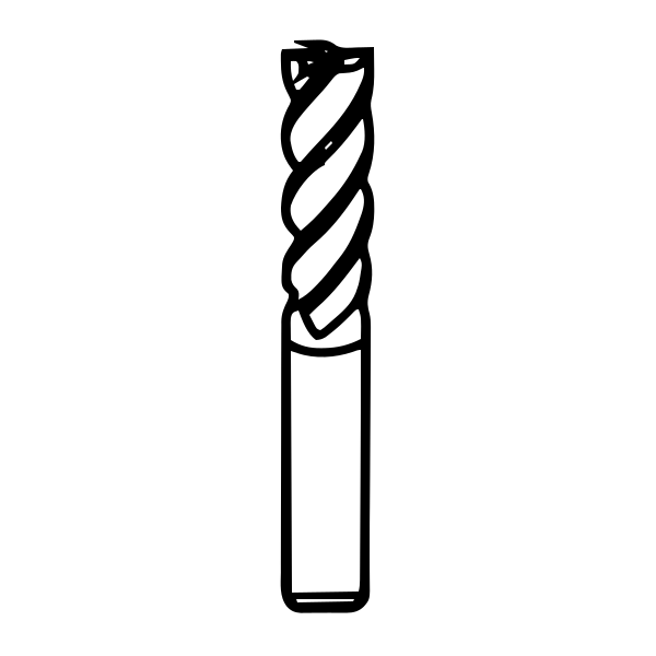
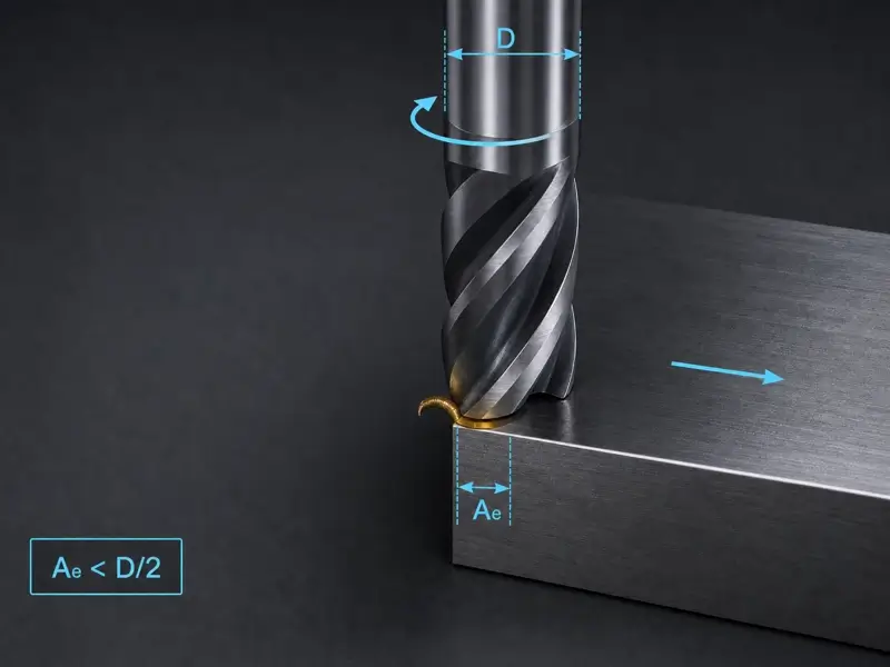
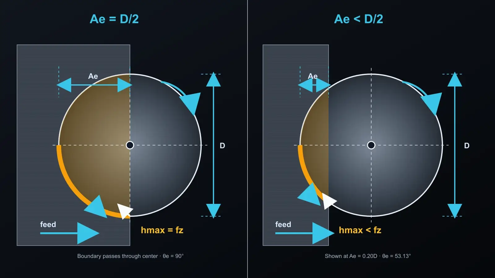
For a 90-degree square end mill on a straight path, radial chip thinning becomes relevant when radial depth of cut, commonly written as Ae, is less than the cutter radius. At half-diameter engagement, the tooth reaches the cutter centerline and can still form a chip whose maximum thickness equals the programmed feed per tooth. Below that engagement, the tooth leaves the cut before reaching the geometric position that would produce the full programmed thickness.
That distinction matters because CAM usually asks for feed per tooth, while the cutting edge responds to actual chip thickness. When Ae is below the radius, those values are no longer equal.
Do not carry this straight-cutter rule into every milling operation. Ball-nose tools, round inserts, chamfer mills and high-feed geometries also create chip-thinning effects, but their approach angle or curved cutting edge changes the calculation. They need geometry-specific data. This article stays with radial chip thinning for a 90-degree peripheral cutter.
Collect the inputs that actually control the answer
A useful answer begins with the target chip load recommended for the exact tool and work material. A generic chart or a multiplier copied from another toolpath does not establish that target.
| Symbol or value | Meaning | Source |
|---|---|---|
| D | Effective cutting diameter | Tool drawing or technical data sheet |
| Ae | Programmed radial depth of cut | CAM toolpath |
| Cl | Target maximum chip thickness | Application data for the exact tool and work material |
| z | Effective tooth count | Tool specification |
| n | Programmed spindle speed | Speed calculation and machine limit |
| Path type | Straight, internal arc or external arc | CAM geometry |
If you are still selecting the tool rather than calculating a specific cut, the solid carbide end mill collection is a navigation point for comparing available cutter families. It is not evidence that a particular tool or parameter suits the job; confirm the individual tool data before using it.
Use the effective cutting diameter requested by the selected calculation method, not automatically the shank diameter. Also record the units. Mixing millimeters with inch-based chip-load data produces a clean-looking but meaningless result.
Calculate from target chip thickness, not from a memorized multiplier
The calculation should run from the chip thickness the edge is intended to see back to the feed command the control needs.
First, confirm that Ae is below D/2. If it is not, radial chip-thinning compensation is not needed for the straight, 90-degree case described here.
Second, enter D, Ae and the selected target chip load into a calculator or formula set that explicitly handles radial chip thinning. Such tools return either a radial chip-thinning factor or the corrected feed per tooth. Recalculate whenever engagement changes; accepted calculator guidance defines the factor through the relationship among chip load, feed per tooth, diameter and radial depth. For a worked width-of-cut reference, see DAPRA’s radial chip thinning guide; treat its multipliers as geometry references, not a replacement for exact tool data.
Third, convert corrected feed per tooth to table feed:
Table feed = corrected feed per tooth × effective tooth count × spindle speed

Keep the roles separate. Target chip load is the desired maximum chip thickness at the edge. Corrected feed per tooth is the larger programmed tooth advance needed, under this geometry, to create that target thickness. Table feed is the resulting linear machine command.
This is why a vendor chart can be useful without being universal. It may provide the geometric factor for a defined width-of-cut ratio, but it does not choose the target chip load, prove the tool geometry, account for runout, or certify that the machine can execute the result.
Treat arcs as path problems, not straight-line cuts
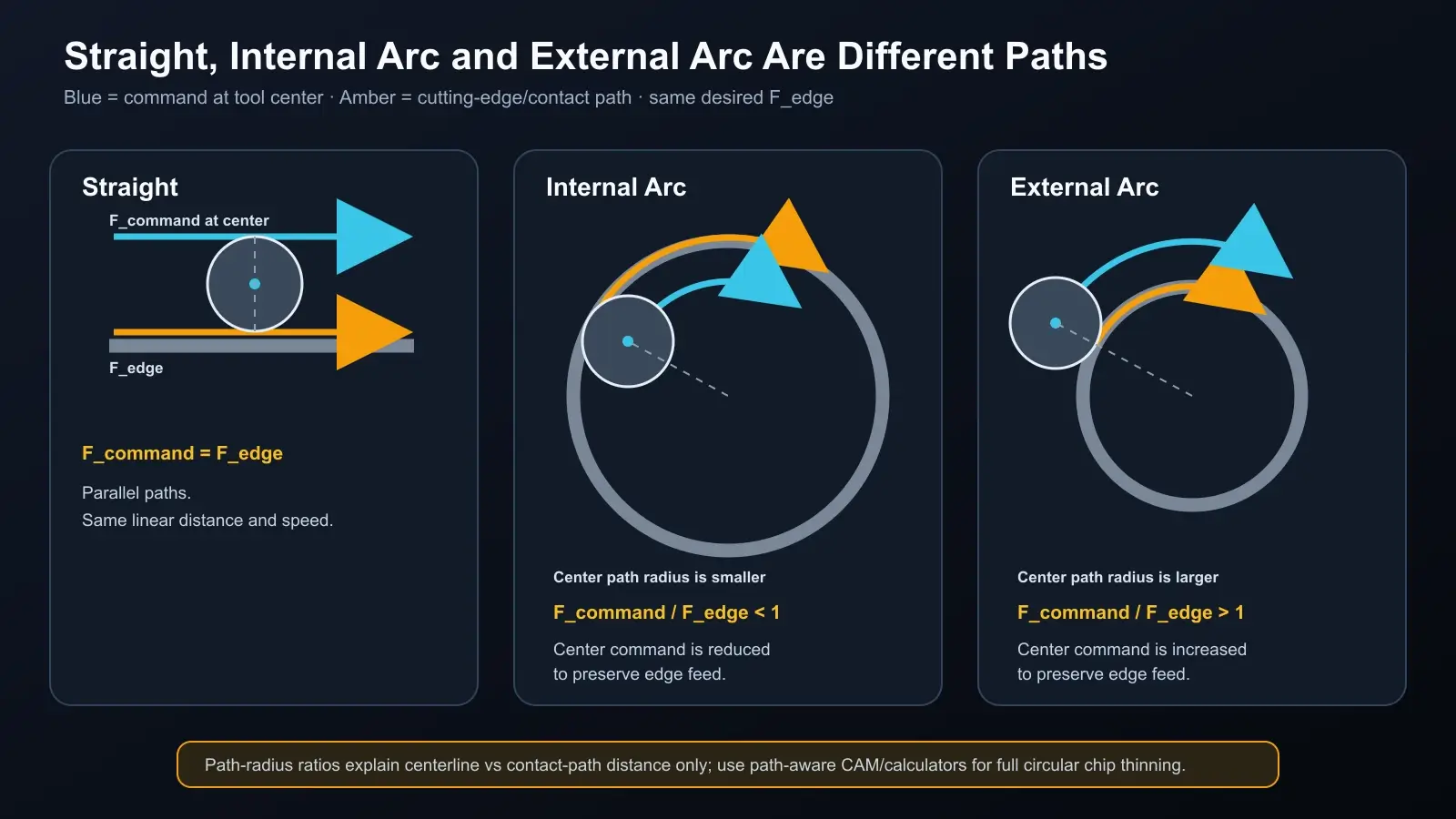
Circular interpolation adds another layer. Accepted calculator guidance separates straight moves from internal and external circular interpolation rather than treating them as one case. A straight-line radial-thinning factor alone therefore does not complete the feed calculation for an arc.
Use a calculator or CAM function that explicitly distinguishes straight, internal circular and external circular interpolation. Enter the relevant cutter and path diameters in the requested units, and verify whether the returned value applies at the tool center or at the cutting edge. The accepted Iscar calculator documentation, for example, separates those path types rather than treating every move as straight.
If the software does not disclose how it handles arc feed, do not stack a manual radial multiplier on top of an unknown automatic correction. Establish which layer owns each adjustment first.
Prove the correction in the machine
Treat the calculated feed as a controlled starting point.
Begin by checking holder condition, stickout, workholding and chip clearance. A corrected chip thickness does not cure an unstable setup. Then confirm that spindle speed, commanded feed and power are within machine capability.
Run the first cut with the planned radial engagement and a defensible axial depth from the same application data. Observe chip formation, sound, spindle load, heat, surface finish and whether chips are being recut. The desired evidence is a stable cutting sound, repeatable load and formed chips leaving the cut—not simply a faster feed display.
Stop if load rises abruptly, chips pack, the tool begins to deflect, chatter appears, or heat concentrates at the edge. Diagnose before changing the program. If you alter RPM, remember that table feed must change with it to preserve the calculated feed per tooth. If you alter Ae, recalculate the thinning factor because the geometry has changed.
Change one variable at a time and record the result. Otherwise, a successful cut cannot tell you which correction worked, and a failed cut cannot tell you which assumption was wrong.
The record does not need to be elaborate. Capture the tool identity, effective diameter, Ae, target chip load, calculated feed per tooth, RPM, table feed and path type beside the observed result. That preserves the conditions behind the setting and makes the next adjustment traceable instead of turning one successful cut into an unsupported shop-wide rule.
Common mistakes that make compensation unsafe
The first mistake is copying a multiplier because the width of cut “looks close.” The factor depends on the ratio of engagement to effective diameter, and the target chip load still depends on tool and material.
The second is confusing low feed with low cutting force. Once chip thickness falls below a useful cutting range, rubbing and heat can increase even though the programmed number appears conservative.
The third is combining radial compensation with a ball-nose or high-feed calculation. Those tools involve approach-angle effects; multiplying two unrelated factors can overload the edge.
The fourth is ignoring path geometry. A straight move, an internal pocket arc and an external contour do not place the cutting edge on the same path radius.
The fifth is accepting the arithmetic without testing the setup. The calculation defines an intended chip condition; the proof cut establishes whether the actual process can produce stable cutting, formed chips and repeatable load.
Conclusion
Radial chip thinning is a geometry problem before it is a feed problem. Confirm that a 90-degree peripheral cutter is below half-diameter engagement, use the documented target maximum chip thickness, calculate the corrected feed per tooth from actual D and Ae, convert it to table feed, and use path-aware logic for arcs. Then validate the result in the machine. A multiplier is only as trustworthy as the geometry, tool data and proof cut behind it.