



Flat-Bottom Drill vs End Mill: How to Choose for the Hole and Its Entry
Choose a flat-bottom drill when the job calls for axial hole machining and its design suits the entry condition. Choose an end mill when you need to prepare a flat entry, cut sideways or interpolate the hole. An irregular pre-cast opening can make the entry condition more important than the finished-hole shape.
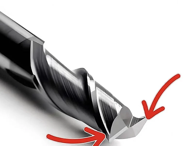
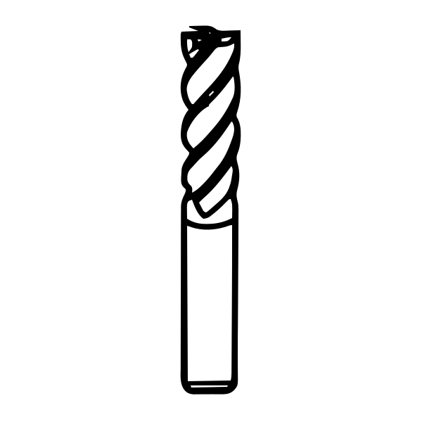
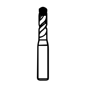
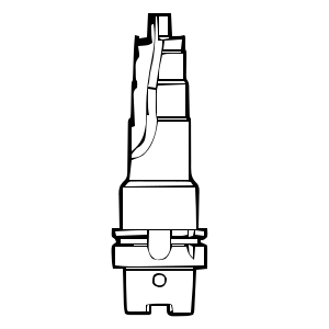
The tools can look similar in a drawing. Both may have two flutes and a flat-looking end, but their centre geometry, peripheral edges and guiding features serve different jobs. Start with the cutting motion and the stock the edges will meet.
First separate drilling from milling
A drill normally advances along its own axis to make a hole close to its cutting diameter. An end mill cuts laterally to produce a wall, slot or profile; a suitable centre-cutting design can also enter axially. An end mill can make a larger hole by circular or helical interpolation when the tool and process permit it.
This distinction matters when replacing a tool. An end mill used to interpolate a flat-bottom hole is not performing the same operation as a flat-bottom drill fed straight into it. Substituting one tool into the other's cycle can change engagement, chip evacuation and the finished floor.
For an unidentified tool, obtain an end view, a side view and its tool drawing. Two-flute end mills are also used in metal cutting, so flute count alone cannot settle the question.
What to inspect when the tools look alike
| Inspect | Flat-bottom drill | End mill |
|---|---|---|
| End view | Check the centre and end-edge geometry specified for axial drilling. | Confirm whether the design is centre-cutting and which axial entry methods are permitted. |
| Side view | Identify the guiding margins and flute space associated with the drilling design. | Identify the peripheral cutting edges and relief used for lateral cutting. |
| Intended motion | Usually an axial drilling cycle close to the tool diameter. | Lateral cutting or an approved interpolation and entry path. |
The views help you ask the right questions; the tool drawing and approved operations settle them. A flat-looking end or two flutes alone is not an identification method.
Look at the blank before choosing the drill
Imagine a casting with an irregular opening where the centre is already empty but stock remains around the intended hole. A pointed drill enters this opening differently from solid material: its centre may have nothing to engage while an outer part of one cutting edge meets stock.
If the stock is uneven, one edge may carry a load while the opposite edge is partly or entirely unloaded. That changing engagement can deflect the tool or damage an edge. A finished-part drawing rarely shows enough detail to assess this start.
Ask for the pre-cast or pre-machined opening at the entry and farther down the hole. Check whether it is centred, how much stock remains around it, and where interrupted contact occurs. A centred pilot hole, an offset cast opening and solid stock are three different starting conditions.
Why a flat-bottom drill can help
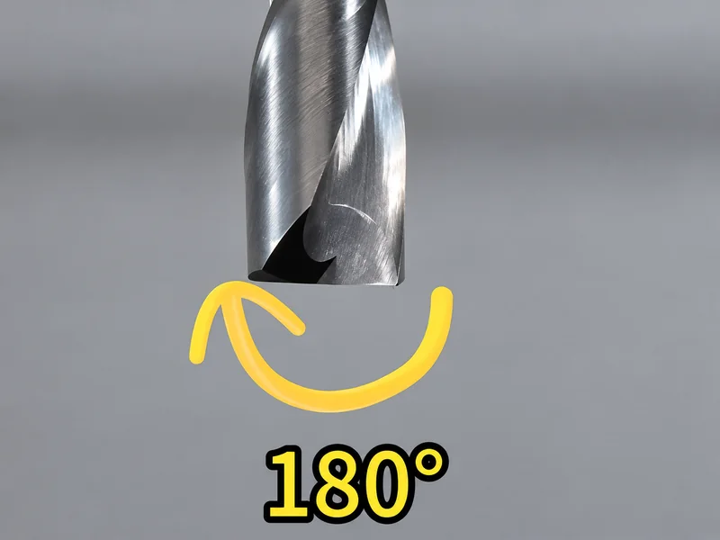
A flat-bottom drill brings its end cutting edges into contact without a projecting conventional drill point. In an application designed around counterboring, a hollow entry or another interrupted surface, that end geometry can provide a more suitable way to engage the remaining stock.
Its benefit comes from the complete drilling design: end-edge geometry, edge strength, guidance, flute space and the permitted cutting conditions. Commercial flat-drill families are specifically offered for applications including counterboring, inclined surfaces and half-holes. This is a positive reason to consider them when an ordinary drill starts poorly.
The opening can still load one side first. Flat geometry does not remove radial force or make an offset opening symmetric. Use the blank geometry to select a drill intended for that entry, and verify location and straightness on the first part. A flat drill improves an appropriate drilling process; it is not a substitute for boring when a misplaced hole needs its axis corrected.
Choose the entry strategy that fits the part
Solid material with a regular, flat entry
Use a conventional pointed drill as the starting option when it can meet the depth, tolerance and bottom-shape requirements. The centre and lips engage in the intended sequence, and there may be no benefit in paying for a different end geometry. If the final floor must be flat, compare a flat-bottom drill with a separate finishing operation.
An irregular opening with stock around an empty centre
Compare the opening with the application limits of a suitable flat-bottom or specialised drill. The aim is to cut the remaining stock in an axial operation without relying on a drill point engaging solid material at the centre.
If the opening extends beyond the desired finished-hole boundary, no material-removal process can replace the missing wall. If stock is available but the axis must be established more accurately, assess boring rather than expecting a change in drill-point shape to repair the location.
A sloped entry where a local flat is permitted
Mill a local entry surface, then drill from that surface. This is useful when the extra cut fits the component design and simplifies a troublesome one-sided start. The end mill performs the lateral preparation; the drill then performs the axial hole machining.
The cost is an additional operation and possibly a tool change. For a short run, that can be easier to justify than developing a special drill. For repeated production, compare the accepted cycle time with a qualified direct-drilling route.
A sloped entry that must remain as drawn
Consider a drill explicitly intended for the slope and material. A suitable flat drill may allow direct entry, but the start can require different feeds from a flat-surface cut. Use that design's entry guidance and distinguish the initial partial engagement from the later full cut.
A specially ground point is another design route to discuss with the tool engineer. The centre, chisel edge and point form influence the first contact; changing them may address a particular entry problem. Specify the proposed geometry and the actual slope. A four-facet or pyramid-like appearance alone is not evidence that a point will grip every inclined surface without walking.
Where direct entry remains unstable, revisit local preparation or a milling route instead of repeatedly changing drill material while preserving the same engagement.
A practical selection table
| Condition | Starting route | Reason and tradeoff |
|---|---|---|
| Solid stock, regular entry, no flat-floor requirement | Conventional drill | Use the normal drilling route without adding a special geometry unnecessarily. |
| Axial hole with a specified flat floor | Flat-bottom drill, or drilling followed by floor finishing | A single tool may simplify the cycle; a separate finish can provide more control over the required floor. |
| Irregular pre-cast opening or interrupted entry | Flat-bottom or specialised drill rated for that engagement | Match the end geometry to the remaining stock; verify location and edge condition. |
| Inclined entry with room for preparation | Mill a local flat, then drill | Regularise the start at the cost of another operation. |
| Inclined entry that must remain intact | Qualified direct-entry drill or an engineered point design | Avoid altering the part, but validate the entry conditions and tool life. |
| Side cutting, pocketing or an interpolated hole | End mill with an appropriate toolpath | Use milling motion and suitable entry geometry rather than treating the cutter as a drill. |
Specify what “flat bottom” must achieve
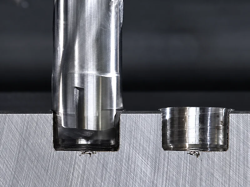
A seating surface, usable hole depth and a controlled corner radius are separate requirements. Put them on the drawing. A nominally flat end mill can have end relief that leaves a floor profile after a straight plunge; a finishing path may be needed. A flat-bottom drill likewise has a defined centre and corner geometry that must suit the required floor.
Check whether the hole is complete after this operation or still needs boring, reaming or another finish. Preserve the intended allowance. A clean-looking hole is not enough if its position, floor or remaining stock prevents the next operation from succeeding.
Make the first-part check answer the selection question
Record the blank condition alongside the tool and cutting cycle. Inspect entry damage, hole location, diameter, depth and floor shape as applicable. When an edge chips during entry, compare where it first contacted the stock before changing the whole process.
The decisive information is the combination of tool geometry, motion and blank condition. Once those are clear, a flat-bottom drill, an end mill or a two-operation route becomes a reasoned choice instead of a guess based on appearance.