



Thread Milling Feeds and Speeds: Calculate the Cutter Path
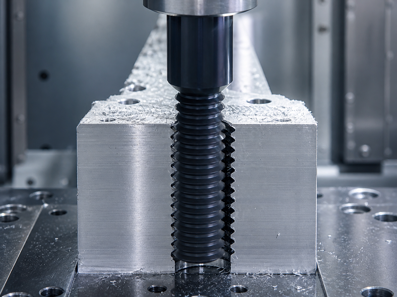
Thread milling feeds and speeds are not finished when a calculator returns RPM and linear feed. Those values describe cutting at the tool’s active diameter. The CNC, however, commands the center of the cutter around a helical path. On an internal thread, that center path is smaller than the diameter at which the cutting edge works. On an external thread, it is larger. If the CAM system expects a path-corrected feed and receives an uncorrected edge feed—or corrects a value that was already corrected—the chip load is no longer what the programmer intended.
A defensible setup therefore has two calculations and one verification. First calculate spindle speed and cutting-edge feed from data for the exact cutter and work material. Then translate that feed to the cutter-center path when the programming system requires it. Finally inspect the posted motion and prove one thread before releasing production.
Define the geometry before calculating
Start with the thread, not the calculator. Record the thread form and nominal size, pitch or threads per inch, tolerance class, internal or external location, right- or left-hand direction, number of starts, usable thread depth, relief space and inspection method. Define the pre-hole or outside diameter and confirm that the tool can enter, cut to depth and leave without colliding with a shoulder.
Next identify the cutter by manufacturer and exact item number. Record its cutting diameter, number of effective teeth, cutting length, minimum bore if applicable, single-profile or multiple-form design, shank and holder. Do not substitute nominal thread diameter for cutter diameter. Do not assume two tools that make the same thread use the same surface speed, chip load or radial-pass strategy.
The carbide thread mill collection can help identify candidate tool families. The selected model’s drawing and application data still control the program; the collection link is not evidence that every listed family fits every material, depth or thread form.
Complete the condition tuple before choosing cutting data: workpiece material and hardness, heat treatment, scale or interruption, coolant method, holder type, measured runout, stickout, spindle range, feed capability, acceleration limits and fixture rigidity. Also document what the CAM field means. Some systems ask for feed at the cutter edge and calculate the centerline feed. Others expect the centerline value directly. That single interface detail decides whether a separate arc correction belongs in the calculation.
Tool-to-thread size ratio deserves explicit attention. As the cutter occupies more of an internal thread diameter, the difference between edge-path circumference and center-path circumference becomes proportionally larger. The correction can therefore matter much more in a small bore with a relatively large cutter than in a large bore with a small cutter. A cutter that physically fits the pre-hole may still leave little room for a gentle entry arc or chip evacuation. Check those constraints before optimizing cycle time.
Thread depth changes the mechanical picture as well. Longer stickout increases access but reduces stiffness; a deep blind thread also limits chip escape and exit clearance. These are selection and setup constraints, not terms that a feed equation can repair. If the chosen tool cannot meet reach and rigidity together, return to tool selection instead of compensating with an arbitrary feed override.
Calculate spindle RPM from the actual cutter
Use cutting speed from the exact toolmaker under conditions that match the cutter, coating, work material and operation. A forum value or a value for a different tool family can be a question to investigate, but it is not a production input.
For inch units:
The common shop approximation n = (SFM × 3.82) / Din expresses the same relationship. For metric units:
Here D is the actual cutting diameter used by the supplier’s data, not the thread diameter or cutter-center path diameter. Vc is in metres per minute; SFM is surface feet per minute.
Check the result against the machine’s usable spindle range under load. If the calculated speed exceeds the limit, use the achievable RPM and recalculate feed from that actual speed. Keeping the old linear feed while lowering RPM raises chip load. Raising RPM without adjusting feed lowers it. The pair belongs together.
Convert feed per tooth into cutting-edge feed
When the source gives feed per tooth, calculate the linear feed at the active cutting diameter:
z is the number of effective cutting teeth and fz is feed per tooth. The output is inches per minute when fz is inches per tooth, or millimetres per minute when fz is millimetres per tooth.
Verify what counts as an effective tooth for the selected cutter. A multiple-form thread mill may show many thread profiles along its length, but those profiles are not automatically the flute count in the feed equation. Use the manufacturer’s definition. Likewise, if the source already gives a linear feed for a stated RPM, do not multiply it by RPM or flute count again.
This result is the desired cutting-edge feed. It preserves the selected chip load at the tool circumference during straight-line engagement. Circular interpolation introduces a second radius, so the CNC command may need another step.
Translate cutting-edge feed to the cutter-center path
Linear feed is distance per time, but the distance convention must be named. If the CAM or control defines feed from the planar XY arc component, the active cutting edge and cutter center complete their different circumferences in the same time. Their planar feeds are related by the path-diameter ratio:
This is the central circular interpolation issue: identical angular progress does not mean identical linear distance at two radii.
That diameter ratio is not a universal three-dimensional helical-feed formula. If programmed F represents resultant distance along the full helix, axial lead per orbit also contributes to path length. With axial advance L per orbit, the corresponding length ratio is:
Symbols: Fc,XY and Fe,XY are planar center-path and cutting-edge feeds; Fc,h and Fe,h are the corresponding resultant helical-path feeds; Dc and De are their path diameters; and L is axial advance per complete toolpath orbit.
Use the planar ratio only when CAM/control documentation defines feed from planar circular motion. Use the helical-length relationship only when it defines feed along the resultant 3D path. Many systems handle this internally, so the entered field, generated center path and posted feed mode must be checked together.
For an internal thread, the center path lies inside the active cutting-edge path. Its diameter is smaller, so the centerline feed is normally lower than edge feed when the control commands the cutter center. For an external thread, the center travels around a larger circle than the active inward-facing cutting edge, so the required centerline feed is normally higher.

That direction check is useful, but it is not enough to program from memory. The diameter used for D_edge_path depends on how the toolmaker and CAM define the active thread-cutting path—major, minor, pitch or another effective diameter. Cutter compensation, programmed contour and control interpretation can shift responsibility between CAM and machine. Use the selected tool documentation and inspect the generated center path.
The safest question is not “Which correction formula do I always use?” It is “What physical path does this feed describe, and which path does this software command?” Write both answers beside the calculation. Then apply the ratio once.
Thread-Milling RPM and Planar Path-Feed Calculator
Enter cutting data for the exact cutter and material, then enter the active cutting-edge path diameter and the cutter-center path diameter. The last result is a planar path-ratio check only. Use it only when the CAM or control expects centerline feed and has not already applied the correction.
Do not apply the path ratio twice. This calculator does not calculate resultant three-dimensional helical feed, select a cutting speed, or determine which diameter definition your CAM expects.
Keep pitch separate from spindle feed
Thread pitch controls axial travel around the helix. For a single-start thread, one 360-degree orbit of the cutter around the work advances one pitch along the thread axis. That orbit is a toolpath revolution, not a spindle revolution. The spindle may rotate thousands of times while the cutter center completes one orbit.
For a multi-start thread, lead and pitch are not interchangeable: lead is the axial advance over one revolution of the thread, and equals pitch multiplied by the number of starts. The CAM cycle must represent the intended start count and handedness. Never “correct” an axial pitch error by changing feed per tooth.
Pitch also affects the true three-dimensional distance travelled by the center along a helix. Many CAM systems calculate the helical path and its feed behavior automatically. The programmer still needs to confirm the axial endpoint after one orbit, the total number of orbits, start depth, final depth and whether lead-in and lead-out moves remain clear of the part.
Work a symbolic internal-thread calculation
Suppose the exact tool data supplies cutting speed Vc, feed per tooth fz, cutter diameter Dc and effective flute count z for a defined material condition. The internal thread model supplies the active cutting-edge path diameter De, and the CAM toolpath produces cutter-center diameter Dp.
- Calculate n = (1000 × Vc) / (π × Dc) in metric units.
- Apply the machine’s achievable spindle limit if necessary.
- Calculate cutting-edge feed Fe = n × z × fz.
- If CAM expects planar center-path feed, calculate Fp = Fe × (Dp / De). If it expects resultant helical-path feed, use the helix-length ratio with axial advance L instead.
- Enter
Fponce. If CAM expects edge feed and applies the ratio itself, enterFeand do not pre-correct it. - Verify that a 360-degree orbit advances by the specified pitch for a single-start thread.
Because Dp is smaller than De for the internal case, Fp should be smaller than Fe. If the result moves in the opposite direction, stop and inspect the diameter definitions. This symbolic example deliberately contains no recommended SFM, chip load or diameter. Those inputs must remain traceable to the selected tool and condition.
Interrogate the CAM output before the machine
Do not treat a clean simulation image as proof that the parameter meaning is correct. Open the operation definition and posted motion and answer these checks:
- Does the feed field request edge feed, centerline feed or a chip-load input?
- Is arc-feed optimization enabled, and does it act on internal arcs, external arcs or both?
- What center-path diameter does the backplot show at full engagement?
- Does one orbit advance the correct pitch or lead in the intended axial direction?
- Is the milling direction intentional for the chosen internal or external path?
- Do entry and exit arcs establish engagement gradually without striking the opposite wall?
- Is the thread cut in one radial pass or several, and does that match the selected tool guidance?
- Did the post output the expected spindle, feed mode, plane, arc direction and endpoint?
- Are machine RPM, feed, acceleration and interpolation limits respected?
A feed-mode mistake can survive visual simulation. Confirm whether the program is using units per minute, inverse time or another control-specific mode. If cutter compensation or a wear offset will be active, confirm the sign and adjustment convention on that machine before the proof cut.
Compare the CAM display with a simple independent estimate. The predicted center diameter should agree with the backplot, the corrected feed should move in the expected internal/external direction, and the axial endpoint should equal the required pitch or lead after a full orbit. This is not a second CAM system; it is a dimensional reasonableness check that can catch a wrong tool diameter, duplicated compensation or unit mismatch before metal is cut.
Prove one thread and adjust size deliberately
Simulation and collision checking come first. At the machine, verify tool identity, measured runout, holder seating, work offset, pre-hole, clearance, coolant and the loaded program revision. Follow the shop’s approved dry-run or single-block policy; do not improvise around safety interlocks.
Make one proof feature in representative material. Record actual spindle speed and feed override, then inspect the thread with the specified gage or measurement method. Check size at more than one depth when the thread is long enough for taper to matter. Examine finish, burrs, load trend, chips, sound and the cutter edge.
If the thread is consistently tight or loose while form, finish and tool condition are stable, alter the designated cutter-radius, wear or toolpath offset according to the CAM/control convention. Make a measured adjustment, recut or cut the next proof feature, and record the response. Do not change feed merely to move thread size. Feed is a cutting-load variable; path radius is the direct size variable.
When size changes with depth, investigate runout, deflection, holder condition, stickout, pre-hole alignment and radial-pass strategy before applying one global offset. A single offset can hide one end of a tapered thread while worsening the other.
Diagnose a bad result by evidence, not instinct
| Observed result | Discriminating check | First controlled response |
|---|---|---|
| Consistent tight or loose size | Confirm gage method, tool diameter record and offset sign | Adjust the designated path-radius or wear offset; hold cutting parameters stable |
| Size changes with depth | Measure runout, stickout, holder seating, pre-hole alignment and deflection | Correct the mechanical cause or revise a documented radial-pass strategy |
| Chatter or faceted finish | Check rigidity, engagement, entry, runout and whether centerline feed was double-corrected | Remove the identified setup/path error, then test one parameter change |
| Rapid wear or edge damage | Confirm material condition, actual surface speed, coolant delivery and chip recutting | Restore the source condition tuple; reduce one load variable only with evidence |
| Poor finish with acceptable size | Inspect chips, burr formation, edge condition, exit motion and feed mode | Correct evacuation or motion first; then qualify a single feed/speed change |
This order matters. An incorrect center path cannot be cured reliably by slowing the spindle. Excessive runout cannot be normalized by averaging the measured thread size. Change the variable that directly explains the observation and predict what the next measurement should do.
Release a traceable thread-milling process
A released setup should preserve the thread specification and inspection method; tool manufacturer, item number, diameter and flute definition; cutting-data source and revision; work material and condition; RPM and edge-feed calculations; center-path diameters and correction responsibility; CAM operation and post revision; entry, exit, pass and coolant choices; actual machine commands; active offsets; proof-cut results; and the accepted adjustment window.
That record turns a successful thread from a lucky program into a repeatable process. It also makes the next investigation faster: the programmer can see whether a changed tool, material, path diameter, software option or machine limit invalidated the original thread milling feeds and speeds.