 Skip to content
 High-Precision Machining Solution for ADC12 Aluminum Steering Gear Housing
This case study focuses on the complex machining of an automotive steering gear housing using high-performance PCD tools. The primary challenge lies in maintaining high dimensional accuracy across multiple hole angles while managing the inherent instability of thin-walled ADC12 aluminum castings. By implementing a comprehensive PCD tooling solution, Sundi ensures the precision and stability required for high-volume automotive production.
Project Overview
The workpiece presents several technical hurdles that standard ISO tools often fail to address:
Thin-Walled Construction: The housing is prone to vibration and thermal deformation during high-speed cutting.
Complex Geometry: Multi-angle hole distribution requires tools with exceptional reach and stability.
Space Constraints: Limited clamping space prevents the use of angle heads, necessitating custom-length tooling solutions.
Material Abrasiveness: High-silicon ADC12 causes rapid tool wear, leading to frequent downtime.
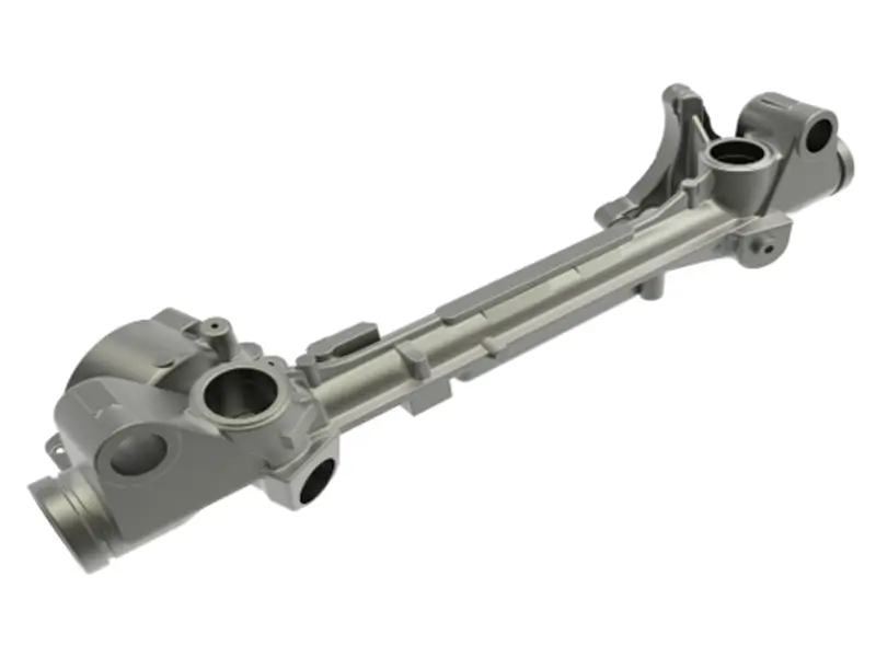
| Component Name | Steering Gear Housing |
| Workpiece Material | ADC12 Aluminum Alloy (High Silicon Content) |
| Industry Segment | Automotive Tier 1 – Steering Systems |
| Equipment Type | 5-Axis CNC Machining Center (or 4th Axis setup) |
| Spindle Interface | HSK63 High-Rigidity Interface |
| Core Challenges | Thin-walled structure, clamping deformation, and multi-angle hole distribution. |
Sundi’s Integrated Tooling Solution
We developed a complete suite of customized PCD tools to optimize every stage of the machining process:
Station A: Precision Internal & External Step Boring
This stage focuses on efficient stock removal for internal and external steps within the steering gear housing.
The Challenge & Solution:
Restricted Access: Solves a critical “mounting lug” interference issue where standard tool holders fail due to high collision risks.
Ultra-Thin Profile: Features a customized Ultra-Thin Body designed specifically to clear narrow gaps while maintaining rigidity.
Simultaneous Efficiency: Increases throughput by processing internal and external steps in a single pass using a stable HSK63 interface.
Cutting Parameters:
| Operation (OP) | RPM (rev/min) | Vc (m/min) | fz (mm/Z) | Number of Teeth (Z) |
| Step Boring | 3,700 | 692 | 0.2 | 2 |


Station B: Integrated Drilling & Counterboring (Boss Hole)
Efficiency-driven design that combines two operations into a single high-speed pass.
The Challenge & Solution:
Consolidated Workflow: Traditionally requires two tools (drill + chamfer/counterbore). Our solution integrates drilling and spot facing into one step.
Rigid Construction: Features a Butt-Welded design, combining a tough steel shank with a carbide/PCD head for superior vibration damping and cost-effectiveness.
High-Speed Capability: Engineered for extreme cutting speeds (Vc 1500 m/min) in ADC12 aluminum.


Station C: Master Cylinder Deep Bore Finishing
High-stability solution designed for small-diameter, deep bore applications.
The Challenge & Solution:
Deep Hole Precision: Machining deep, small-diameter holes often leads to tool deflection and vibration. This tool is engineered specifically to overcome these rigidity challenges.
Integrated Guide Pads: Features a specialized Support design with guide pads that stabilize the tool within the bore, ensuring exceptional straightness and surface finish.
Dual-Function: Efficiently combines precision boring and chamfering operations in a single tool layout.


Cutting Parameters:
| Operation | RPM (rev/min) | Vc (m/min) | fz (mm/Z) | Z (Teeth) |
| Boring | 3000 | 1200 | 0.1 | 4 |
| Chamfering | 3000 | 600 | 0.05 | 4 |
Station D: Deep Reach Helical Milling (Restricted Access)
High-removal solution for deep cavities where angle heads are restricted.
The Challenge & Solution:
Space Constraint: The application requires a deep cut (~110mm) in a confined space where standard angle heads cannot be used due to fixture interference.
High MRR Design: Features a Helical Insert Arrangement (spiral design). This “Corn Cob” style layout allows for aggressive material removal (high MRR) and stabilizes cutting forces over the long overhang.
Heavy Roughing: Specifically engineered for large stock removal in a single efficient pass.


Station E: Precision Multi-Step Fine Boring
Streamlined finishing for complex stepped bores with extreme cutting speeds.
The Challenge & Solution:
Cycle Time Reduction: Engineered with a Multi-Edge Design specifically to minimize machining time per part.
Tool Consolidation: Integrates multiple small steps into a single complex profile. This replaces multiple standard ISO tools, significantly reducing tool change time.
Optimized Geometry: Features varied geometric angles to ensure consistent, high-precision surface finishes across different bore diameters.


Station F: Modular Multi-Function Compound Tool
Ultimate versatility featuring a detachable milling head and exchangeable cartridge system.
The Challenge & Solution:
Complex Geometry: The part requires boring, bottom facing, and large-diameter face milling. Doing this with separate tools would drastically increase cycle time.
Cost-Effective Maintenance: Features a Modular Design where the milling head is separate from the shank. Crucially, it uses Exchangeable Cartridges for the milling inserts. If a crash occurs or seats wear out, you replace only the cartridge, not the expensive tool body.
High-Density Cutting: The multi-edge design allows for higher feed rates and reduced cycle times across all three operations.


Cutting Parameters:
| Operation | RPM (rev/min) | Vc (m/min) | fz (mm/Z) | Z (Teeth) |
| Boring | 5500 | 1500 | 0.07 | 4 |
| Bottom Face | 5500 | 1500 | 0.01 | 4 |
| Face Milling | 6500 | 5500* | 0.2 | 4 |
Station G: High-Speed Lightweight Trepanning Compound Tool
Advanced lightweight design utilizing 3D printing technology for extreme cutting speeds.
The Challenge & Solution:
Advanced Manufacturing: To solve the rigidity issues inherent in thin-walled tools, we utilized 3D Printing and Laser Cutting technologies. This allowed us to create a complex, lightweight geometry that is impossible to manufacture with traditional methods.
Structural Optimization: The optimized design features a specialized Rib/Web Structure . This reinforcement drastically increases rigidity and dampens vibration, even with the tool’s thin walls.
Cost-Smart Design: Adopts a Split Modular Design where the cutting head is separate from the body, reducing long-term consumable costs.

Cutting Parameters:
| Operation | RPM (rev/min) | Vc (m/min) | fz (mm/Z) | Z (Teeth) |
| Trepanning | 9500 | 3500 | 0.18 | 2 |
| Drilling | 9500 | 2350 | 0.12 | 2 |
Station H: Integrated Drill-Mill-Bore Compound Solution
A 4-in-1 powerhouse capable of drilling from solid and finishing in a single pass.
The Challenge & Solution:
Drilling from Solid: Unlike standard reamers that require a pre-hole, this tool is designed for Solid Machining . It features an exchangeable drill insert tip to handle the heavy removal work cost-effectively.
4-in-1 Process Integration: Drastically reduces cycle time by combining four distinct operations: Drilling + Rough Boring + Fine Reaming + Back Chamfering.
Hybrid Technology: Smartly combines two technologies:
Indexable Inserts for the drill tip (lowering consumable costs).
Brazed PCD Body with a multi-edge design (Z=4 for Reaming) to ensure high-precision surface quality and extended tool life.


Tool Capabilities & Specs:
| Operation Zone | Function | Effective Teeth (Z) | Feature |
| Tip | Drilling | 2 (Insert) | Replaceable Tip for Cost Saving |
| Body | Rough & Fine Bore | 4 (PCD) | High Stability Reaming |
| Shank/Neck | Back Milling | 2 (PCD) | Back-Chamfering Capability |
Proven Results & Efficiency
-
Cycle Time Reduction
Decreased from 200 seconds to 140 seconds per part.
-
Enhanced Stability
Eliminated vibration-related scrap on thin-walled sections.
-
Tool Life Extension
Multi-blade PCD designs tripled the interval between tool changes compared to previous solutions.
-
Cost Efficiency
Replaceable-tip designs and composite tools significantly lowered the cost-per-part.
Cost Per Part (CPP) Analysis
Lower percentage indicates higher cost-efficiency per part.
Wuxi Sundi Precision Tools Co.,LTD
- +86 18168312921
- +86 18168312921
- +86 18951588639
- info@sundicuttingtools.com
Our team is here to help you! We provide personalized solutions to meet your unique needs. Contact us to learn more.
Sundi's custom PCD solutions solved our complex interference issues and boosted our production efficiency by 15%.
Robert Miller Senior Manufacturing Engineer