Ir al contenido
Hard milling speeds and feeds: build a starting point without copying the wrong cut
A published hard-milling speed and feed is useful only when its source conditions resemble the cut in front of you. Before using one, match the workpiece hardness, cutter and edge system, radial and axial engagement, toolpath, runout, effective stickout, rigidity, spindle capability and thermal plan. If several conditions differ, treat the value as an example rather than a machine setting.
That distinction matters most when a programmer is trying to improve a poor result. Low radial engagement can make the actual chip much thinner than the programmed feed per tooth suggests, but a feed change cannot correct excess reach, runout, poor workholding or chip recutting. Check the system before compensating in CAM.
Start by matching the operation, not a number
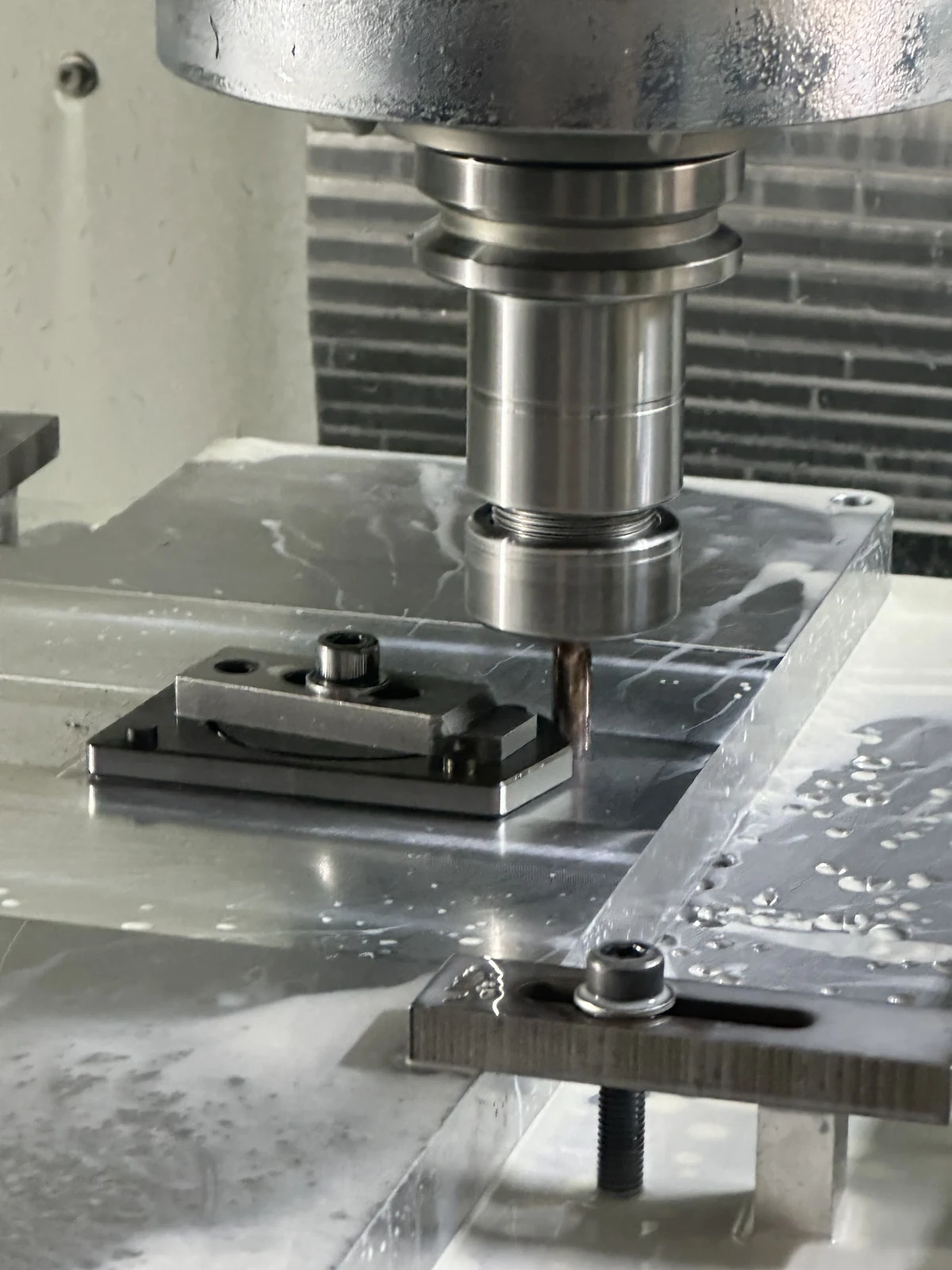
Hard milling couples the cutter, the machine and the engagement more tightly than a generic speed-and-feed table can show. A change in tool diameter, edge preparation, coating, hardness, radial engagement, corner path or spindle behavior changes the load and heat that the tool sees. Runout and stickout matter for the same reason: the tooth that carries more load may not be the tooth the program assumes is carrying it.
| Before copying a published value | What must travel with it | If the condition does not match |
|---|---|---|
| Material y dureza | Workpiece grade, hardness and stock condition | Keep the value as reference evidence and obtain a starting point for the actual material. |
| Cutter and engagement | Diameter, edge system, radial and axial engagement, corner path and toolpath | Recalculate the cut instead of transferring the original feed directly. |
| Machine and setup | Holder, measured runout, effective stickout, rigidity and spindle capability | Correct or document the setup difference before compensating in CAM. |
| Thermal and chip plan | Dry, air or coolant strategy and chip evacuation | Validate the thermal cycle and chip path with the selected tool system. |
Keep the conditions in this table beside the chosen starting value. If a later trial changes the engagement, setup or tool system, that record shows what is no longer comparable. Obtain the initial cutting data for the actual tool and hardened material from the tool supplier, then verify it on the machine.
Read radial engagement before changing feed
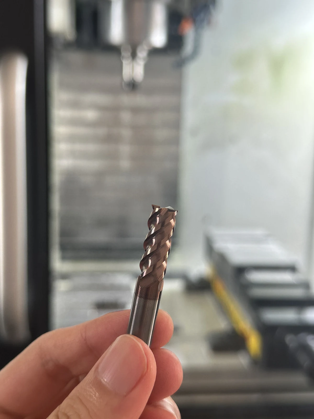
When radial engagement falls below 50% of cutter diameter, radial chip thinning begins. The commanded feed per tooth is no longer the same thing as the maximum chip thickness formed in the cut. If the programmer leaves the programmed feed unchanged while the radial engagement becomes small, the tool can cut a thinner chip than intended.
That is why a high-efficiency toolpath should not be tuned by copying the feed from a full-width cut. The engagement geometry has changed. The correct response is to calculate or verify the compensation within the limits for the actual cutter, material, runout, machine and supplier guidance, then confirm the result with the same feature and tool.
As radial engagement becomes smaller, the same programmed feed per tooth can produce a thinner maximum chip. Check the compensation method for the actual cutter geometry and toolpath. A correction calculated for one engagement must be checked again when the width of cut, corner path or cutter changes.
Chip thinning is also not an excuse to ignore a weak setup. A higher programmed feed can increase the tooth load, and the usable result still depends on tool strength, machine dynamics, runout and the supplier maximums. If the cut sounds unstable, leaves inconsistent marks or damages the edge, first determine whether engagement is the issue or whether the tool is being driven by a mechanical fault.
Match the starting parameters to the actual cut
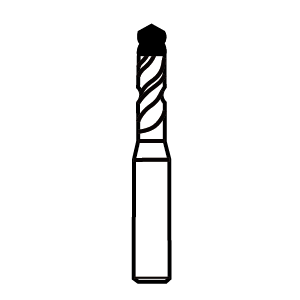
When using a fresa de metal duro, start with cutting data for the selected tool and workpiece material. Before applying it, confirm the material grade and hardness, cutter diameter and edge geometry, radial and axial engagement, toolpath, tool overhang, and cooling or air-blast conditions.
A parameter set developed for one hardened-steel application may not suit another. Changing the cutter type, engagement or setup rigidity changes the conditions under which the original data was established. Treat unmatched data as a reference for further checking rather than a ready-to-run setting.
For finishing, evaluate surface quality separately from material-removal rate. Feed per tooth, cutting speed, tool diameter, axial depth and corner radius can affect the result, and their effects depend on the tool and setup. A productive roughing setting does not automatically provide the required finish. Research on hardened-steel milling supports evaluating these variables within the tested conditions rather than transferring a tool ranking or parameter set.
Troubleshoot the system before compensating in CAM
If a hard-milling cut is failing, use the result to decide which branch to inspect rather than changing several variables at once.
Start with effective reach and rigidity. Excess overhang, a flexible holder or a flexible workpiece can make the tool deflect and change chip load around the cut. Then check runout and seating. A tool or holder problem can concentrate load on one tooth, which can look like a feed problem even when the programmed feed is unchanged.
Next look at chip evacuation and recutting. Recut chips can damage the edge, affect finish and make the cutting sound misleading. Then inspect the edge condition and tool suitability. A worn or unsuitable tool should not be kept alive by increasingly aggressive program changes.
Only after those checks should the program be adjusted. Change one documented variable, repeat the same feature and compare the sound, tool condition, finish and load behavior. If the change produces a better result, keep the conditions with the record. If it does not, return to the preceding branch instead of stacking another adjustment on top of an inconclusive test.
Coolant belongs in the same conditional workflow. Evaluate dry cutting, air blast or coolant with the selected tool system, thermal cycle and chip-control need. A change in fluid delivery can change both chip evacuation and the thermal conditions at the edge, so validate it as a process change rather than applying a blanket wet-or-dry rule.
Validate one controlled change
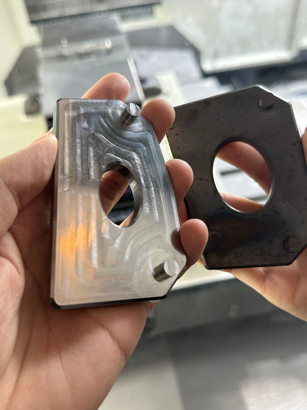
Before the next trial, record the material and hardness, cutter and holder, measured runout, effective stickout, radial and axial engagement, toolpath, feed per tooth, spindle speed and thermal strategy. Record the symptom too: edge damage, finish, sound, chip behavior or load. That baseline prevents a successful-looking change from being assigned to the wrong cause.
Then make one change that answers one question. If radial engagement is the question, hold the rest of the setup stable and verify the chip-thinning adjustment. If tool failure is the question, inspect reach, runout, holding and chip recutting before changing feed. When the result is repeatable on the same feature, the retained record is more useful than a number copied into a general table.
Keep each successful result tied to the recorded program, tool, engagement, setup and thermal conditions. Outside those conditions, validate again before treating the retained value as a shop-wide standard.