



Ranurado con fresa de extremo: entrada, viruta y control dimensional
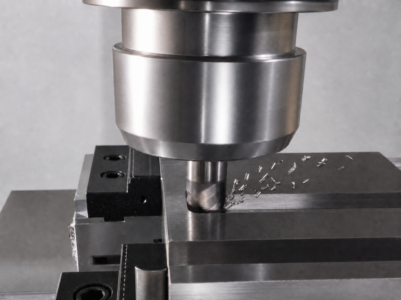
El ranurado sitúa la fresa entre dos paredes. En una ranura ciega o durante bajadas axiales, los filos frontales generan también el fondo actual. Una pasada del ancho de la fresa implica contacto a anchura completa y menos salidas para viruta que un corte lateral abierto. Funciona si ranura, fresa, entrada, máquina y evacuación se tratan como sistema.
No empiece copiando una profundidad genérica, sino por la ranura. Una pasante poco profunda con entrada abierta difiere de una ciega profunda con radio de fondo acabado. Clasifique la forma y elija pasada a ancho completo, desbaste menor y acabado, contacto controlado u otro proceso. Cualifique después la ruta en la máquina real.
Definir la ranura antes de elegir la fresa
«Ranura» describe una forma, no un plan completo. Anote estas propiedades en plano o ficha:
- pasante o ciega;
- abierta en un borde o cerrada en ambos extremos;
- recta, curva o conectada a una cavidad;
- profundidad total y acceso útil superior;
- tolerancia de paredes, posición y rectitud;
- fondo plano, radiado o controlado de otro modo;
- radios en extremos y entre pared y fondo;
- estado del bruto, del material y superficies interrumpidas;
- salida de virutas y superficies accesibles para inspección.
Los datos de búsqueda pueden abreviar la tarea como ranurado con fresa de extremo, pero esa frase no define la ruta. La geometría sí.
El cuadro siguiente es un punto de partida, no una tabla de parámetros:
| Condición observada de la ranura | Ruta candidata a evaluar | Qué debe demostrar el corte de prueba |
|---|---|---|
| Ranura poco profunda, extremo abierto, salida suficiente | Pasada a ancho completo o desbaste menor | Estabilidad de carga, ancho, posición de trayectoria y acabado de paredes |
| Exigencia estrecha de ancho o acabado de paredes | Fresa menor y pasadas separadas de acabado de paredes | Sobrematerial por pared, compensación, simetría y ancho final |
| Ranura cerrada sin entrada abierta | Rampa, hélice, penetración con corte al centro o acceso pretaladrado verificados | Carga de entrada, marca de fondo, evacuación y holgura |
| Ranura profunda o estrecha | Longitudes escalonadas, desbaste de contacto controlado u otro proceso | Alcance, flexión, evacuación, forma de paredes y estado de herramienta |
| Ranura pasante de geometría recta simple | Fresa de extremo, de ranurar/sierra u otro proceso adecuado | Rebabas, soporte en salida, ancho, acabado y economía del ciclo |
La ruta depende también de cantidad y riesgo. Una solución manual puede servir para una reparación única, pero no para producción repetida. A la inversa, una trayectoria CAM compleja puede aportar poco en una ranura corta abierta sobre máquina rígida. Elija la ruta menos compleja que cumpla el plano y pueda verificarse.
Separe ancho y posición. Una ranura puede medir bien y estar desplazada respecto a su referencia. Puede estar bien en un extremo y desviarse longitudinalmente. La inspección debe cubrir ambos resultados.
Por qué el ranurado a anchura completa es exigente
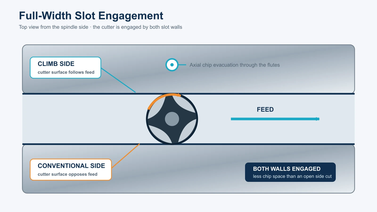
El contacto completo elimina material en todo el diámetro nominal. Un lado trabaja en concordancia y el otro en oposición. El arco y el contacto bilateral crean una carga distinta del fresado lateral con un lado abierto.
Las virutas se forman en el canal recién creado. Al profundizar, las paredes limitan la salida lateral. Pueden circular, recortarse o compactarse bajo los canales. Si el material tiende a formar filo recrecido, la adhesión cambia filo efectivo y espacio. La carga puede subir rápidamente antes de romper.
El número de labios forma parte del compromiso. Más labios pueden aumentar sección del núcleo y filos, pero dejan menos volumen por viruta. Menos labios dan más espacio sin garantizar rigidez ni estabilidad. Diámetro, canal, material de herramienta, longitud de montaje, material, régimen del husillo y evacuación determinan la adecuación.
El descentramiento desequilibra la operación nominal. Un labio puede quitar más material, cargar más y marcar una pared de otro modo. La flexión añade asimetría. Las fuerzas opuestas no se cancelan sobre un eje perfecto, especialmente al variar contacto y movimiento de máquina, portaherramientas y pieza bajo carga.
Por eso un diámetro igual al ancho nominal no garantiza la ranura deseada. Descentramiento, flexión, holgura, error de trayectoria, filos y recorte cambian ancho, forma y posición. En una fresadora manual flexible o router ligero, la fresa también puede tirar lateralmente de la trayectoria.
El paso axial determina cuánto filo y canal trabajan bajo la abertura. Más profundidad aumenta la viruta en un paso restringido. Un paso menor no es automáticamente seguro si el avance por diente es demasiado bajo y roza, o quedan virutas. La condición completa debe proceder de datos del modelo y pruebas.
Elegir la estrategia de desbaste y acabado
No hay una única ruta correcta. La elección debe facilitar el control final manteniendo viruta y carga dentro de la capacidad del conjunto.
Cuándo considerar una pasada a ancho completo
La pasada completa es sencilla con ranura accesible, evacuación eficaz, máquina y portaherramientas rígidos, fresa autorizada para ranurar y conjunto cualificado para ancho y acabado. Entrada abierta y poca profundidad reducen restricciones, sin eliminar la prueba.
Verifique que la fresa genere fondo y extremos requeridos. Una plana deja su propia geometría de esquina; una radiada cambia la transición fondo/pared. No puede crear una esquina interna menor de lo que permite su geometría.
Use datos exactos de ranurado, no valores de fresado lateral de la misma página. El contacto total cambia la ventana recomendada. Sin datos para material, alcance o clase de máquina reales, solicite orientación o cualifique una condición conservadora bajo supervisión controlada.
Cuándo el acabado separado de paredes da más control
Una fresa menor puede desbastar el centro dejando material en paredes y extremos. Pasadas separadas establecen después paredes y ancho final. Permite compensar y evacuar mejor durante el acabado.
No es automáticamente superior. El desbaste debe dejar material uniforme y el acabado cortar suficiente para evitar roce. Orden y dirección influyen en fuerzas, rebabas y medida. Si el desbaste se desvía mucho, una pared puede tener poco material y la otra demasiado.
Registre material por pared e inspeccione el desbaste si tolerancia o valor lo justifican. Use diámetro real y compensación controlada. La mitad de la diferencia nominal entre herramienta y ranura no corrige automáticamente descentramiento, flexión o geometría de máquina.
En placa fina, el corte completo puede tirar o vibrar incluso poco profundo. Puede requerir apoyo posterior, material sacrificial u otra secuencia. El plan debe controlar también el recorte liberado por la ranura pasante.
Cuándo el contacto controlado u otra fresa cambia la economía
Una trayectoria CAM puede abrir con contacto radial parcial mediante arcos repetidos o movimiento trocoidal. Da espacio y limita el arco, pero exige ancho suficiente, geometría adecuada y salida CAM verificada. También cambia longitud, demanda de movimiento y acabado.
No llame «adaptativa» a toda oscilación suponiendo carga controlada. Inspeccione contacto real en entrada, esquinas, cambios y limpieza final. Una trayectoria suave en el centro puede enterrar la fresa en una transición.
Pretaladrado o desbaste por penetración pueden quitar el centro si herramienta y máquina lo admiten. Agujeros próximos también generan entrada interrumpida y crestas que cargan desigualmente. Conserve material de acabado y verifique la aptitud de broca o fresa para el movimiento.
En ranuras rectas pasantes, una fresa de ranurar o sierra puede dar una ruta más corta y rígida. En profundidades o fondos difíciles, herramientas escalonadas, EDM u otro proceso pueden ser más económicos. Esa frontera se retoma abajo.
Elegir el conjunto de herramienta a partir de la ranura
Parta de ancho, fondo y esquinas y compruebe longitud de corte y alcance. Los canales deben cubrir profundidad sin rozar la transición del mango; mantenga salida y longitud de montaje tan cortas como sea práctico.
Una gran longitud de corte no garantiza rigidez útil. Un cuello reducido da holgura pero cambia rigidez. Un canal largo admite más contacto axial y aún puede flexionar por fuerzas radiales. Verifique el plano exacto, no solo la longitud total.
Elija canales, preparación, sustrato y recubrimiento para material y ranurado. El espacio importa, pero no basta una regla universal de labios. Pequeños routers rápidos en aluminio, centros pesados en acero y fresadoras manuales de reparación tienen límites distintos de husillo, par, evacuación y rigidez.
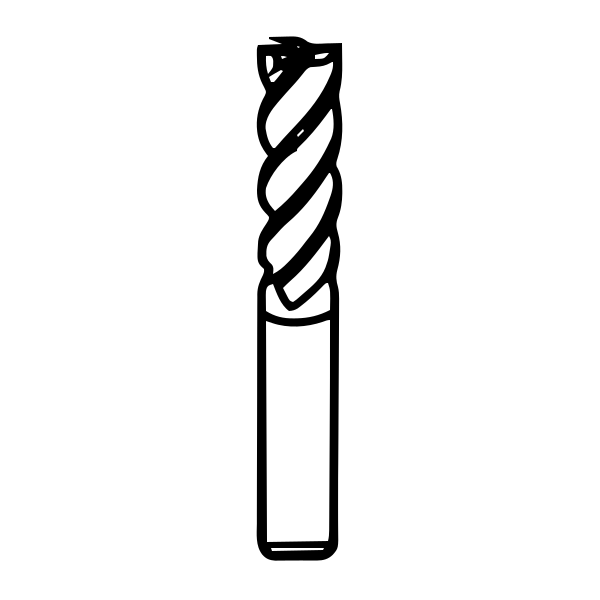
Una primera búsqueda de familia puede empezar por la gama de fresas de metal duro. La página de gama no verifica que una fresa pueda penetrar, ranurar con cierto contacto, alcanzar profundidad o mantener tolerancia. Use el plano y los datos de aplicación del modelo.
Trate portaherramientas y fresa como conjunto. Registre tipo, sujeción, longitud de montaje y descentramiento medido donde sea útil. Compruebe envolvente en aproximación y profundidad total. En trabajo profundo, el canal puede librar mientras portaherramientas, tuerca o transición del mango tocan la pared.
Verifique también máquina: régimen y par, avance, holgura o estado de ejes, capacidad de fluido/aire, cerramiento, sujeción y rigidez de pieza. Si algo no admite la ruta, cámbiela antes de calcular órdenes.
Tratar la entrada como operación propia
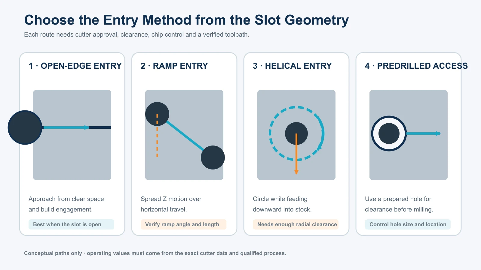
La entrada suele tener fuerzas y virutas distintas del avance estable. Un programa correcto después puede fallar en la primera penetración.
La entrada abierta suele ser más sencilla: la herramienta llega desde espacio libre y aumenta contacto. Bruto, abrazaderas y retiradas deben dejar espacio sin golpear una esquina sin apoyo.
La penetración recta exige corte al centro y condiciones permitidas. «Corte al centro» indica capacidad geométrica, no cualquier profundidad o avance seguros. En el centro la velocidad tiende a cero, la viruta se forma distinto de la periferia y debe subir por canales. Use datos aprobados y capacidad real de empuje y evacuación.
La rampa distribuye Z sobre recorrido horizontal. Ángulo, base de avance, dirección y longitud deben ajustarse a datos y ranura. Una rampa corta puede seguir siendo empinada; un vaivén puede cruzar repetidamente sus virutas si evacua mal.
La entrada helicoidal necesita diámetro libre y condición verificada de isla central o solape. En una ranura estrecha puede no caber. Un pretaladrado da holgura, pero tamaño, posición, salida y transición deben programarse deliberadamente.
Las etiquetas CAM no son prueba. Simule la trayectoria real y revise referencias Z, compensación de centro o filo, lado de entrada, sobrematerial de fondo y holgura. Una operación de ranura o contorno puede referirse distinto a parte superior, inferior o centro. Verifique en vacío o bloque a bloque según el procedimiento seguro del taller y con geometría real.
Cualificar juntos virutas, órdenes y corte de prueba
Obtenga velocidad y avance por diente de los datos exactos para la condición de ranurado correspondiente. Calcule después órdenes en unidades claras.
Para unidades en pulgadas:
RPM = (SFM × 3.82) ÷ diámetro de fresa en pulgadas
Para unidades métricas:
RPM = (1000 × velocidad de corte en m/min) ÷ (π × diámetro de fresa en mm)
El avance de mesa es:
Avance de mesa = RPM × número real de labios × avance por diente
Si las RPM calculadas superan el rango útil, use RPM alcanzables y recalcule el avance de mesa. Compruebe par, potencia y límites de avance. No mantenga el avance al cambiar RPM salvo aprobación expresa del avance por diente resultante.
Fije paso axial, avance de rampa o penetración y contacto controlado desde la misma fuente del modelo o proceso cualificado. Los ejemplos de foros del expediente usan otras máquinas, materiales, herramientas y evacuación: contexto de fallos, no ajustes transferibles.
Defina evacuación antes de cortar. Inundación, suministro interno, aire, niebla, aspiración u otro método deben adecuarse a material, máquina y controles de seguridad. Lo importante es despejar fondo y canales a la profundidad elegida. Mojar solo la parte superior puede no bastar.
Haga la prueba permitiendo observar carga, sonido, virutas y transición de entrada. Pare ante atasco, adhesión, carga creciente, vibración inestable, movimiento, contacto del portaherramientas, daño o trayectoria incierta. No siga para «ver si se despeja». Una ranura atascada puede pasar rápidamente de mal acabado a rotura.
Después, limpie sin dañar e inspeccione la herramienta. Anote si daño o adhesión afectan un labio, la punta o toda la banda axial. Esos patrones distinguen descentramiento, daño de entrada, recorte y sobrecarga general.
Interpretar los errores de ranura como patrón
Mida ancho en varias posiciones y, si se puede, profundidades. Mida por separado la posición desde la referencia de control. Inspeccione paredes, fondo, radios, rebabas y bordes de salida.
Una ranura ancha con marcas repetidas de un labio requiere otro diagnóstico que un ancho correcto desplazado. Verifique diámetro real, descentramiento, compensación y eje programado antes de cambiar valores.
Si el ancho varía arriba o abajo, examine flexión, alcance, geometría de husillo/ejes, movimiento y medición. Una entrada acampanada puede deberse a entrada inestable, flexión variable o pausa. La variación longitudinal puede implicar ejes, bruto, dilatación, desgaste o virutas acumuladas.
Las paredes pueden diferir porque una se genera en concordancia y otra en oposición. Descentramiento y flexión amplifican la diferencia. Pasadas separadas pueden mejorar el control si queda material suficiente y el montaje no cambia.
Rayas o virutas incrustadas en el fondo apuntan a recorte o mala evacuación. Una marca circular puede venir de penetración, hélice o pausa. Relacione rebabas de salida con apoyo, dirección, filos y material.
Cambie una causa cada vez y mida en los mismos puntos. Un corte más silencioso es un indicio útil, no prueba de ancho, posición, fondo y herramienta aceptables.
Reconocer cuándo la fresa de extremo deja de ser la mejor opción
Ranuras profundas y estrechas combinan alcance largo y salida restringida. Longitud nominal suficiente no garantiza rigidez, volumen ni holgura. No hay un límite universal de profundidad/diámetro para toda herramienta y máquina.
Considere abrir por otro lado, dividir operaciones, desbastar con herramientas progresivamente largas o aumentar el radio. Las longitudes escalonadas preservan rigidez en el desbaste; la más larga trata solo lo necesario. Sigue haciendo falta un plan de unión e inspección.
En una ranura recta abierta, sierra o fresa específica pueden dar rigidez y acceso de viruta. En una ciega, muy profunda, de pequeño radio o pieza endurecida o sensible a deformación, EDM u otro proceso pueden controlarse mejor. Tienen sus propias tolerancias, capa refundida o rebabas, sujeción y costes; no son mejoras automáticas.
Considere hacer la ranura antes de que la pieza quede fina o flexible. El orden puede aportar apoyo imposible de recuperar después. Controle el recorte pasante para que no atrape la fresa ni dañe paredes acabadas.
Abandone esa ruta si no puede verificar salida, interferencia, evacuación, entrada o capacidad de máquina. Bajar solo el avance no resuelve la limitación física.
Registrar la ventana de proceso antes de liberar
Una operación liberada debe identificar forma y ruta. Registre tipo, referencia, ancho/profundidad nominales, fondo/esquinas, identificadores de herramienta/portaherramientas, diámetro real, labios, longitudes de corte/montaje, descentramiento y revisión de datos.
Añada familia de trayectoria, entrada, paso axial, contacto radial controlado si se usa, RPM, avance de mesa, penetración/rampa, compensaciones y evacuación. Guarde versión CAM verificada y cálculos manuales que afecten lado de fresa o referencia Z.
La inspección debe mostrar dónde se midieron ancho y posición, no solo una cifra aceptada. Incluya paredes/fondo, ventana de carga, viruta y filos. Defina ajustes permitidos al operario y cuándo hace falta revisión técnica.
Enumere al final los motivos de recualificación: otro modelo, reafilado, portaherramientas, longitud, estado del material, sujeción, máquina, entrada, profundidad o evacuación. El resultado útil es una ventana medida ligada a un conjunto y ruta. Ese registro hace repetible la operación.