


Hole machining: choose tooling by geometry, interruptions and coolant flow
A hole diameter and a “through” or “blind” label are not enough to select a reliable machining tool. A bore may end inside the part, cross an existing passage halfway down and expose the cutting edges to interrupted contact. Each condition changes a different part of the tool's job.
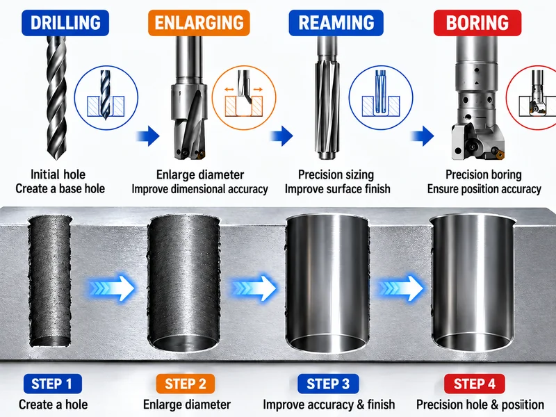
For hole machining, first describe where material is present and where it is missing. Then assess what happens to the cutting edge, coolant and chips as the tool advances. A cross-hole can change both the edge loading and the coolant escape route; solving only one may leave the other unresolved. This article focuses on reaming, enlarging and form-machining existing holes, using Sunditools' internal application experience.
Describe the hole in three views
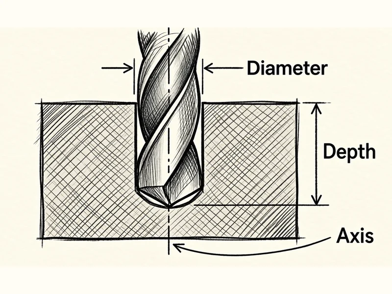
Start at the end of the hole. A blind hole stops within the workpiece; a through hole opens out of it. That distinction identifies a possible forward exit, but says little about the material the tool encounters before reaching the end.
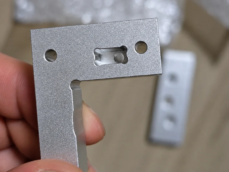
Next follow the tool axis. Is there solid material along the working length, or does the cutting zone encounter an existing cross-hole or cavity before entering material again? Finally, look at edge contact around the circumference. A slot, keyway or intersecting passage may cause a cutting edge to leave the material and strike it again during rotation.
| View | What to identify | Why it matters to the tool |
|---|---|---|
| Hole endpoint | Blind bottom or through exit, including actual clearance beyond the finished length | Available travel and possible chip discharge route |
| Axial path | Material, an existing opening or cavity, then material again | Changes in coolant escape, chip path and cutting engagement along the stroke |
| Circumferential contact | Complete wall or repeated gaps at the cutting zone | Loss and return of edge contact, impact loading and available support |
These descriptions can apply to the same hole. They are not three mutually exclusive hole types. An intersection can affect both the axial path and circumferential contact; interrupted cutting is not restricted to one viewing direction.
Consider a hypothetical blind bore with a side passage near its middle. The finished bore still has a bottom. While the reamer crosses the side passage, however, fluid has another route out and parts of the cutting edge can lose contact. Below the passage, the edge cuts into the bore wall again. Calling this simply a blind hole omits the transition that may determine whether the tool works.
Mark those transitions on the section view before choosing a grade or coolant outlet arrangement. Their position, width and remaining wall support matter more than the label alone.
Follow coolant and chips through the whole stroke
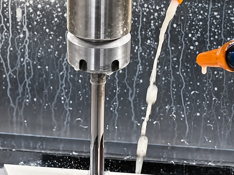
A coolant arrangement that works before an intersection may behave differently at it. Trace the flow at three positions, rather than judging the system from fluid seen at the hole entrance.
Before the cross-hole: check the intended return path
A forward-directed supply may meet material ahead of the tool and return along the available flute space, carrying chips toward the entry. Whether it does so effectively depends on the actual outlet, flute and hole geometry.
At the opening: identify where coolant escapes
The coolant can escape through the side passage or cavity. The return flow that previously helped clear chips may weaken. Fluid leaving the part does not necessarily mean that it is clearing the main chip-producing region.
After the opening: inspect re-entry separately
The cutting edges enter material again. The nearby passage remains a possible discharge route, so coolant and chips may no longer follow the path assumed for an uninterrupted blind bore. Examine this section separately, especially when damage repeatedly appears just beyond the intersection.
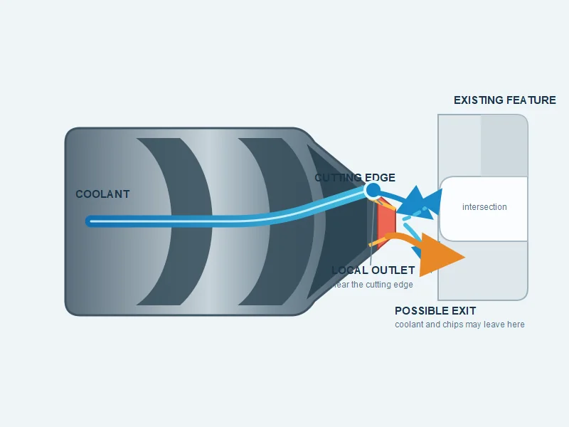
In our application review, we look for a specific conflict: a strong forward jet aimed toward a blocked chip exit. Chips need to return, but the jet can push them back toward the cutting zone. Local recirculation and packing can result. The problem is the combination of jet direction, available exits and chip space, not simply a lack of coolant pressure.
Increasing pressure without understanding the route may leave that conflict unresolved. Check delivery at the working zone and where the chips can actually go.
Where our shallow-angle outlet approach fits
For some tools working across existing passages, our design review considers a local, shallow-angle coolant outlet directed near the cutting edge, with less forward bias than a strongly forward-directed jet. Here, shallow-angle describes the outlet concept; it does not specify a standardized angle or a feature suitable for every tool.
The aim is to supply the chip-producing region without forcing all discharge strongly toward one end. Where material blocks the route ahead, a return path may remain available. Where an opening provides an easier exit, coolant and chips may leave through it. The outlet still has to work with the flute space, edge position and changing hole geometry.
This is a design option to test. It does not guarantee that chips will clear in both directions, and a smaller jet angle will not fix inadequate flute capacity. A tool section and an actual trial are needed to determine the outlet position and direction; the verbal principle alone is not a manufacturing drawing.
Our focus here is on multi-edge reamers, enlarging tools and form tools working in existing holes. These tools can have limited chip space, making the coolant path particularly important. A deep feature or an awkward intersection can make an otherwise workable arrangement unreliable.
Drills are not exempt. A drill making a new hole can also intersect an existing passage and encounter chip evacuation, burr and edge-loading problems. Do not transfer a reamer's outlet concept or operating conditions to a drill without reviewing that tool's cutting geometry and process.
Match edge strength to the interruption
The coolant review does not settle the edge-strength question. In steady cutting, the edge remains loaded and wear resistance is an important part of tool life. When contact repeatedly stops and resumes, the edge also has to survive the loading at re-entry. A tool that wears acceptably in a continuous bore may chip at an interruption before reaching its normal wear limit.
Our internal selection process therefore separates wear resistance from impact resistance. For interrupted features, review the cutting material, edge preparation and support behind the edge together. “Light” and “heavy” interruption should describe the actual contact loss and re-entry conditions. Counting cross-holes alone does not establish severity: one large opening can be more demanding than several small ones.
For PCD, this may mean changing the material grade or grain structure as part of the tool design. It does not justify the rule “coarser grain is always tougher.” The Element Six cutting-material guide describes different grades for chip resistance, abrasive wear and combined demands. Select from the properties of the actual grade and the work material, then verify its behavior at the interruption.
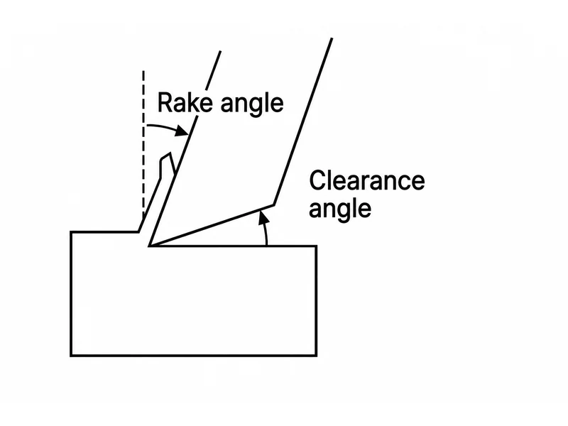
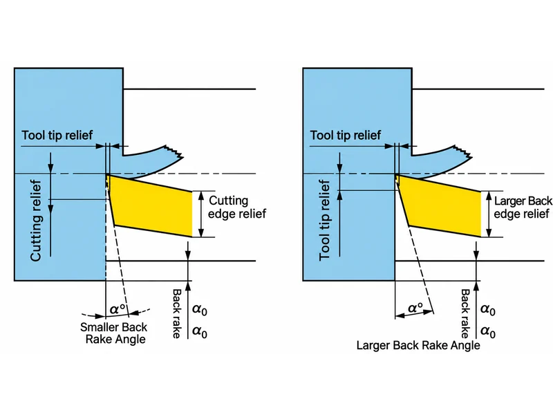
The clearance angle is another design decision. Keeping more support behind the edge can help resist damage, but reducing clearance too far can introduce rubbing. Material, edge geometry and cutting conditions have to be considered together; reducing the angle is not a stand-alone repair.
Use the helix for the problem it can solve
A helical design can influence chip movement, engagement and cutting support. Those effects may improve stability, and progressive engagement can soften how an interruption is encountered. They do not remove the need for an edge that can withstand the resulting loads.
This distinction matters when a tool breaks down at a cross-hole. Better support and a tougher cutting edge address related but different parts of the failure. Selecting a spiral simply because the old tool chipped leaves the material and edge-strength question unanswered.
Use the actual cutting hand, spiral hand and tool drawing when deciding chip direction. Our straight versus spiral flute reamer guide covers that selection. For the hole-condition review, record both the intended chip route and the interruptions the chosen geometry must cross.
Prove the design at the transition
A plain, uninterrupted test hole cannot demonstrate how the tool will behave at a cross-hole. Use a trial feature that represents the actual opening, its position, the remaining material and the required finished length.
Keep the work material, prehole condition, machining allowance, holder, reach and coolant arrangement traceable. During the trial, compare load behavior through the transition where the machine's monitoring allows it. After stopping the machine and making inspection safe, examine the cutting edges and recovered chips. Look for recurring chipping, packing or damage associated with a particular axial position.
Inspect the bore on both sides of the intersection. Check the drawing's size and geometric requirements, surface finish and burr condition at the opening. A good measurement near the entrance does not establish that the portion beyond the interruption is acceptable. If the visible surface indicates rubbing, chatter or recut chips, follow a focused reaming surface finish investigation.
When comparing a revised grade, edge or outlet, keep the other controllable conditions consistent where practical and record any necessary changes. If several features change together, the trial can assess the complete revised tool, but it cannot identify which individual change caused the improvement. Repeat acceptable results before extending the design to a production commitment.
Turn the section view into a trial brief
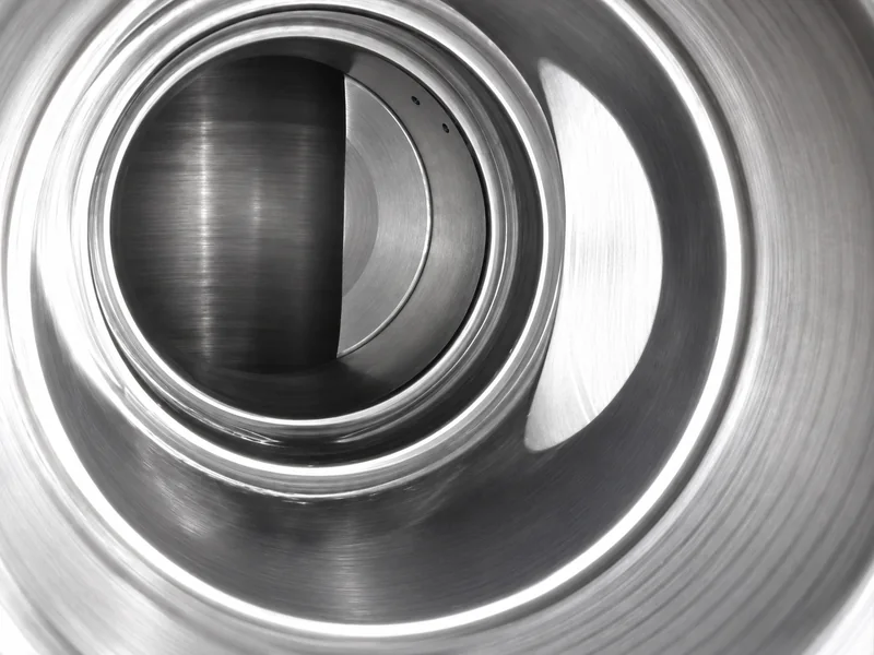
Mark the hole endpoint, every opening the tool must cross and the region where damage or poor finish occurs. Use that section view to review two connected questions: can the edge survive re-entry, and can coolant carry chips away at that position? Grade, edge support, helix and outlet direction are ways to address those questions, not substitutes for describing the feature.
For a custom tool review, discuss the hole geometry and trial results with our engineering team. Sunditools can use the marked section, prehole allowance and available coolant arrangement to assess edge and flute geometry, cutting material, outlet design and suitable operating conditions. The proposed trial should include the actual interruption—not only a plain hole of the same diameter.
For the tool types discussed here, explore our carbide reamers, PCD reamers and customized carbide reamers. Select an option from the actual workpiece, hole geometry and trial requirements.