


Ramping Milling: Types, Applications, Pros and Cons
Ramping is one way to enter closed features by combining lateral movement with descent. A compatible cutter and toolpath can avoid a separate starting hole. This article explains ramping methods, uses, and limitations.
Contents
What is Ramping?
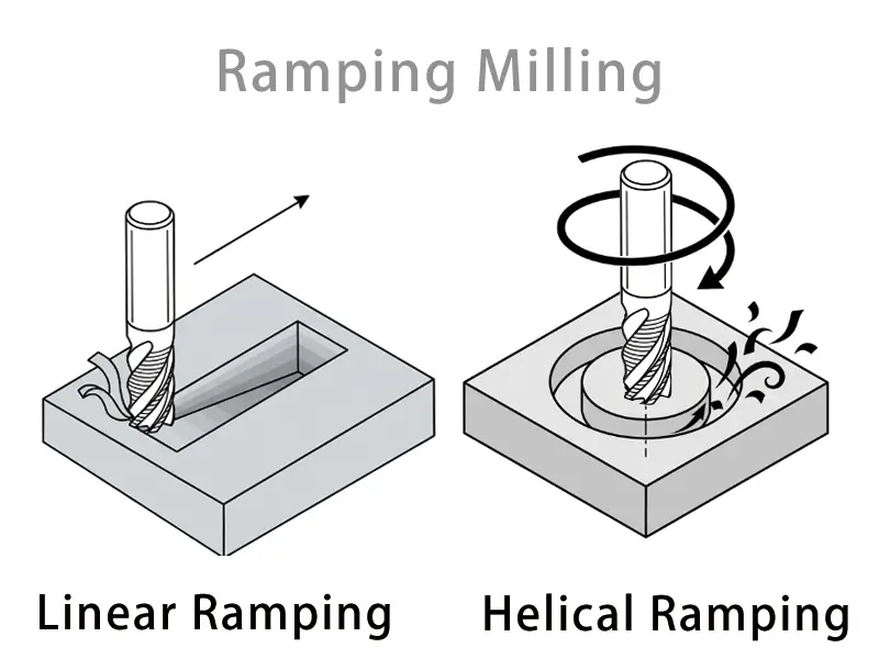
A milling cutter ramps by feeding laterally and axially together. Cutting loads depend on its geometry and engagement, not on a general claim that its sides are stronger than its tip. Use a cutter approved for the selected ramp path.
The following are some of the common situations where ramping is used:
- Entering suitable difficult-to-machine materials with a validated strategy
- Avoiding a separate pilot-hole operation where tool design and feature clearance permit
- Creating closed pockets or cavities without pre-drilling
- Working on intricate designs
Types of Ramping Milling
Here are the types of ramping milling:
Linear Ramping
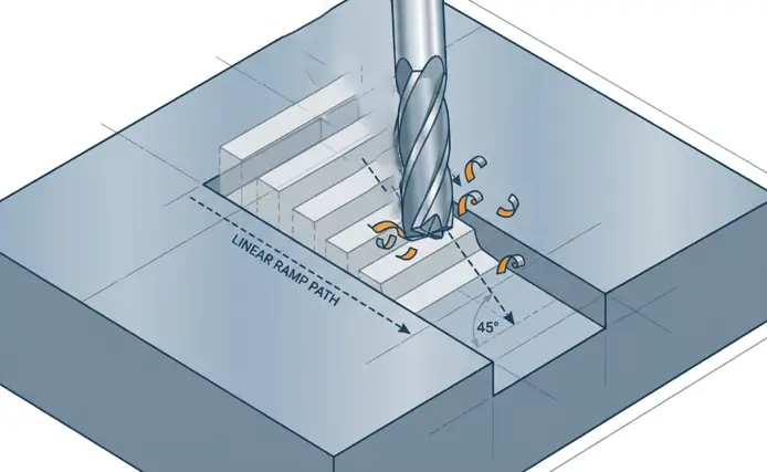
Linear ramping moves the tool forward while it lowers into the material at a steady angle. In this simple path, depth and direction are easy to control.
A linear ramp combines axial descent with lateral travel. Set its angle within the cutter’s limits for the material, diameter, and engagement. A path aligned with X or Y uses two axes; a diagonal XY path may require all three.
- Simple pocket milling
- Shallow slots
- Softer materials
- Basic machining operations
Helical Ramping (Circular Interpolation)
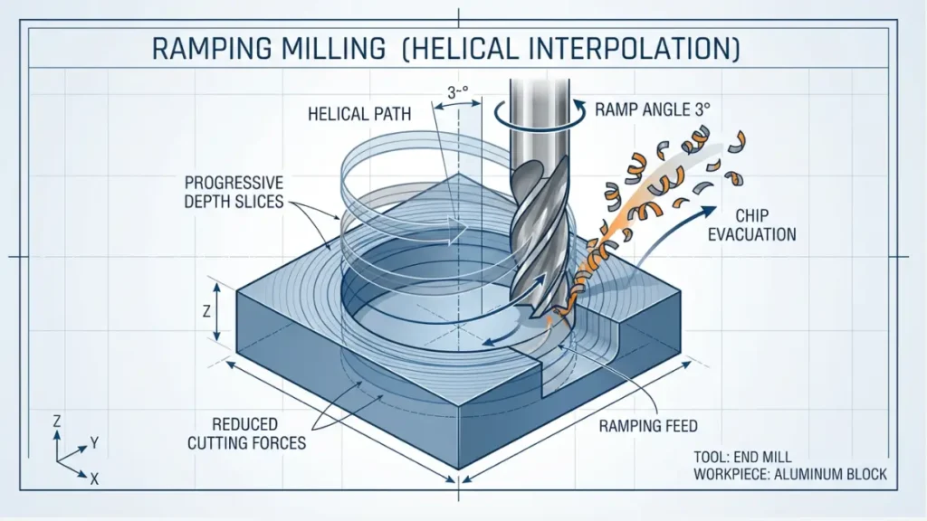
Helical ramping combines an XY circular tool-centre path with Z descent; the cutter also spins independently. Select circle diameter and pitch for the cutter and feature. Good finish and chip evacuation require suitable conditions rather than being automatic.
- Deep holes and cavities
- Hard materials such as steel
- Precision work
- Complex 3D shapes
Benefits of Ramping Milling
Let’s look at some benefits of ramping milling:
Extended Tool Life
A suitable ramping strategy can reduce abrupt entry loading on cutting tools. Actual wear, breakage risk, and cost depend on the cutter, engagement, material, and setup; longer life is not guaranteed.
Improved Surface Quality
Controlled entry can help manage marks and cutting loads. Ramping does not eliminate surface defects or guarantee accuracy; inspect the feature and retain any finishing operations it requires.
Better Chip Removal
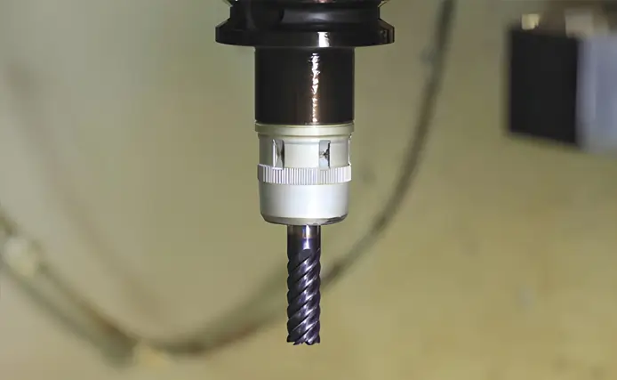
Provide space and a suitable method for chips to leave the cut. Ramping can still pack or recut chips, especially in confined features; monitor evacuation rather than assuming the path prevents buildup.
Reduced Heat Generation
Heat generation and thermal distortion depend on cutting data, engagement, material, and cooling strategy. Ramping alone does not guarantee lower temperature or preserve every material property.
Machining Productivity
Use the ramp feed recommended for the actual cutter and engagement; it may need to be lower than the normal milling feed. Compare total cycle time rather than assuming ramping permits faster cutting without affecting quality.
Limitations of Ramping Milling
While ramping offers a number of advantages, it comes with some tradeoffs.
- The longer entry path can cause increased cycle time, but total production time also includes drilling, tool changes, and finishing. Compare the complete operations rather than entry distance alone.
- Helical paths add programming complexity. Verify the controller, toolpath, and parameter limits before use; a separate advanced software package is not always necessary.
- Machine capability must match the programmed motion. Three-axis helical interpolation requires compatible control and coordinated movement; age alone does not establish whether a machine supports it.
- Finally, ramping requires more space in the workpiece. The tool needs room to create its angled or circular path. Small pockets or tight geometries pose problems where clearance runs short. This spatial requirement limits where machinists can effectively apply ramping techniques.
Materials Suitable for Ramping Milling
Ramping works effectively across diverse materials but requires different approaches based on hardness and machinability.
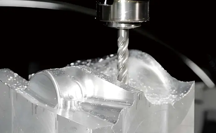
Soft Materials
Hard Materials
For titanium and stainless steel, as well as steels and cast irons, select ramping data for the actual grade, condition, and tool. These are not uniformly hard materials, and one to three degrees is not a universal angle range.
Alloys
Ramping is used in various industries, including the use of titanium alloys in the aerospace industry and the manufacturing of car aluminum engine parts. Similar techniques work for implants where material integrity is most needed. Each of these different materials responds to ramping differently, depending on their thermal properties and their resistance to cutting forces.
Applications of Ramping Milling
Ramping can support creating pockets and cavities directly from solid when the cutter is suitable and has adequate clearance. Check whether a starting hole is still needed for the selected tool and feature.
Slot milling may use a linear ramp where the feature restricts a circular entry. A width below thirty millimetres is not a universal suitability rule, and controlled entry does not eliminate deflection.
Helical ramping is an option for hole making. Compare it with drilling for the diameter, quantity, machine capacity, and finish requirements; cylindrical accuracy must be verified.
Engraving, counterboring, and profile work may use suitable ramp entry paths. Select the method for the specific feature rather than treating ramping as necessary for all detailed surface work.
In micromachining, small tools require carefully controlled engagement and runout. A ramp path alone does not prevent tool failure.
Ramp Milling vs Plunge Cutting
Entry Method
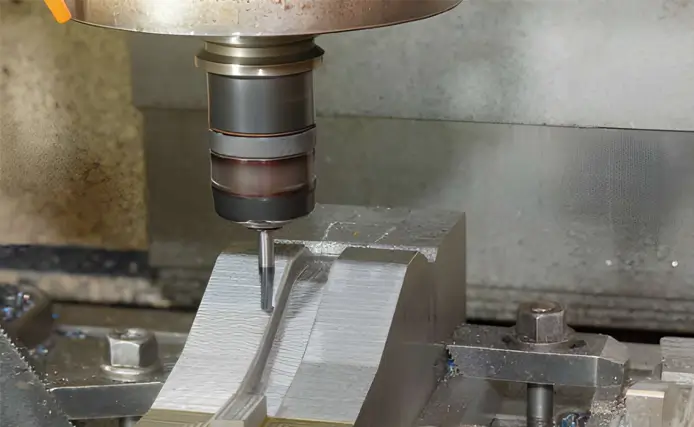
Ramping combines lateral movement with descent. Plunging feeds axially into the material, progressively reaching the programmed depth; it does not engage the full final depth instantaneously. Use a tool rated for the chosen entry method.
Tool Stress
Ramping and plunging produce different load distributions. A purpose-designed plunge tool can be appropriate for axial cutting; do not equate every plunge operation with a damaging impact or assume ramping always extends life.
Cycle Time
A direct axial path is shorter, but cycle time also depends on permitted feed, chip evacuation, required moves, and tool changes. Compare complete cycles; neither method is universally faster.
Machine Requirements
Axial plunging uses a different motion from coordinated ramping. Verify controller functions and toolpath support on the actual machine rather than assuming capability from its age.
Conclusion
Ramping can be a useful entry method where the tool, control, and feature permit it. Compare actual tool life, quality, and total cycle time with alternatives; equipment compatibility and cost savings must be established for the application.
FAQs About Ramping Milling
What is the difference between helical interpolation and ramping?
Helical ramping is one form of ramping. Ramping also includes linear paths, so the terms are not fully interchangeable. Constant-Z circular interpolation is circular milling rather than descending helical ramping.
Which is better: ramping or plunging?
Neither method is universally better. Choose a compatible tool and compare loads, chip evacuation, finish, and total cycle time for the actual feature and machine.
Can you use ramping milling for thin-wall machining?
Ramping may be used near thin walls when support, engagement, and clearance are suitable. Compare force directions and deflection; a shallow linear ramp is not automatically better than a helical entry.
What is a cutter ramp?
Here, a cutter ramp means the programmed entry path. Angle and pitch must remain within the tool’s limits; a shallower angle is not automatically protective if it causes unsuitable engagement or rubbing.
What are the parameters used in ramping milling?
Key parameters include ramp angle or pitch, cutting speed, feed, engagement, and tool-centre path diameter. For internal helical paths, distinguish programmed centre feed from feed at the cutting circumference.
- Ramp Angle: Use the cutter-specific limit and material guidance; the original one-to-ten-degree range is not universal.
- Feed Rate: balances between speed and tool capability.
- Step-down depth: controls the amount of material to be removed per pass.
Validate these settings against the tool specification and actual machining result.
Can ramping be done on 3-axis milling machines?
Yes, provided the machine and controller support the required coordinated motion. Verify interpolation, clearance, and toolpath execution before cutting; having three axes alone is not sufficient.