

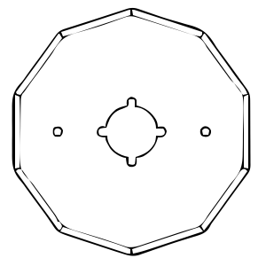
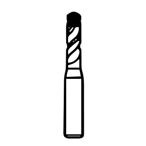
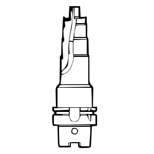


Stainless Steel Cutting Tools: How to Choose Carbide Inserts, End Mills, and Drill Bits
Stainless steels vary in machinability, and suitable tooling and cutting conditions are needed to manage wear, heat, and chip control. This guide explains how to select inserts, end mills, and drills for the actual material, operation, and machine.
Contents
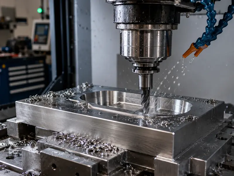
Why Stainless Steel Is Difficult to Machine
Stainless-steel machining behavior depends on the alloy family, material condition, and operation. Work hardening, adhesion, heat transfer, and chip formation can influence tool wear, so use recommendations for the specific grade rather than treating all stainless steels alike.
Work Hardening
Work hardening varies with stainless grade and condition and can be aggravated by rubbing or unsuitable cutting conditions. Use a suitable sharp edge and chip load, and avoid unnecessary dwell. Select depth of cut and entry strategy within the tool and setup limits rather than applying a universal deep-cut rule.
High Toughness
Many stainless steels, particularly austenitic grades, combine substantial toughness with a tendency to adhesion and difficult chip control. These properties vary by grade and condition; choose geometry and parameters for the actual material.
Stainless Steel Grades and Material Properties
Stainless-steel grades and material conditions differ in machinability. Physical-property values alone do not provide a machining rating or determine the correct tool.
Property | 304 Austenitic | 316 Austenitic | 430 Ferritic | 410 Martensitic | 2205 Duplex |
Density | 8,000 | 8,000 | 7,750 | 7,750 | 7,805 |
Melting | 1400–1450 | 1375–1400 | 1425–1510 | 1480–1530 | 1420–1465 |
Heat | 500 | 500 | 460 | 460 | 450 |
Elec. Resistivity | 720 | 740 | 600 | 570 | 800 |
Thermal Cond. | 16.2 | 16.3 | 26.1 | 24.9 | 19.0 |
Modulus of Elasticity | 193 | 193 | 200 | 200 | 200 |
303 Stainless Steel
303 is a free-machining austenitic grade whose sulfur additions improve machinability and chip breaking relative to many standard austenitic grades. Select it only when its corrosion, mechanical, and fabrication properties meet the part specification.
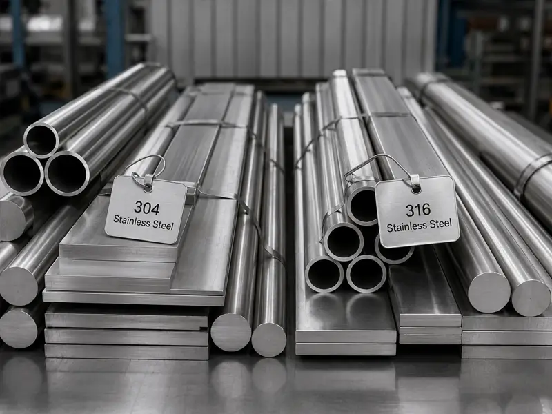
304 Stainless Steel
304 is a widely used austenitic stainless steel. Compared with free-machining 303, standard 304 generally presents greater chip-control and machining challenges; sulfur additions in 303 are an important part of that difference. Use suitable cutting geometry and chip load, and avoid rubbing or unnecessary dwell rather than relying on an instruction to apply steady pressure.
316 Stainless Steel
316 contains molybdenum to improve resistance to certain forms of corrosion. Machinability and tool wear depend on material condition, tooling, and cutting conditions; faster wear than 304 is not guaranteed in every comparison.
17-4 PH Stainless Steel
17-4 PH is a precipitation-hardening stainless steel. Its machining behavior depends on the supplied condition and subsequent aging treatment. Confirm the material condition, hardness, and required machining sequence, then select tooling and cutting data accordingly; heat treatment does not create one universal requirement for a special carbide grade.
Duplex Stainless Steel
Duplex stainless steel has a ferritic-austenitic microstructure; it is not simply two steels mixed together. Its strength and machining behavior call for suitable tooling, rigid support, and grade-specific cutting data, not an undefined instruction to always use slow speed.
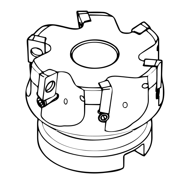
Choosing the Right Carbide Inserts for Stainless Steel
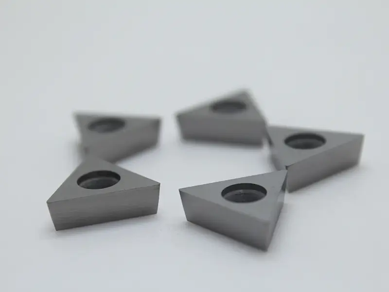
Carbide inserts offer hot hardness and wear resistance for many productive stainless-steel operations. HSS and cobalt-alloyed HSS tools also serve suitable applications. Choose the tool material for the operation, machine, and quality requirements rather than assuming carbide is always superior.
Carbide Insert Grades
ISO M is an application group commonly associated with stainless steels, not one universal insert grade. Check the supplier’s recommendation for the particular stainless family, condition, and operation; some ferritic or martensitic grades may be classified differently in machining guides.
Insert Geometry and Edge Prep
A suitable positive cutting geometry can reduce cutting forces, but edge strength and stability must also be considered. Select the rake, edge preparation, and chipbreaker for the material and feed/depth range. Chip breaking and prevention of work hardening are not guaranteed by rake angle alone.
Coatings for Carbide Inserts
A suitable coating can improve wear resistance, but performance also depends on the substrate, edge preparation, workpiece, and cutting conditions.
TiAlN
TiAlN-type coatings are used in a range of cutting applications. Check the tool supplier’s recommendation for the stainless grade, operation, and cooling strategy rather than treating the coating name alone as a suitability guarantee.
AlTiN
AlTiN-type coatings can provide useful hot hardness and oxidation resistance in suitable applications. Do not describe them as simply becoming harder whenever temperature rises; performance depends on the coating system and operating conditions.
PVD Coatings
PVD (Physical Vapor Deposition) and CVD coating systems are both used on stainless-steel cutting grades. PVD can suit edge preparations requiring thin coatings, but selection depends on the operation and grade rather than a universal preference.
Positive vs Negative Inserts
Positive Inserts
Suitable positive cutting geometry can reduce cutting forces and can benefit slender parts or thin walls. Select the complete insert and holder geometry for the required edge strength and chip control; positive insert clearance alone does not define the effective rake angle or guarantee lower cutting temperature.
Negative Inserts
Negative-clearance inserts can provide robust edge support in suitable designs, but their effective cutting geometry also depends on the chipbreaker and holder. For roughing, select the grade, geometry, feed, and depth of cut within the machine and workholding limits rather than assuming every negative insert is the stronger choice.
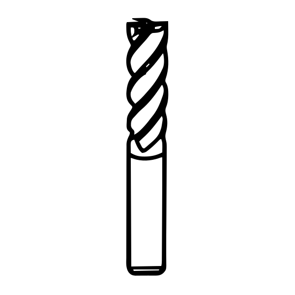
Carbide End Mills for Stainless Steel Milling
For stainless-steel milling, match the cutter and cutting conditions to the alloy, engagement, chip evacuation, and setup stiffness. Address chatter and heat through the complete process rather than expecting the tool to tolerate an unstable setup.
Flute Count and Geometry
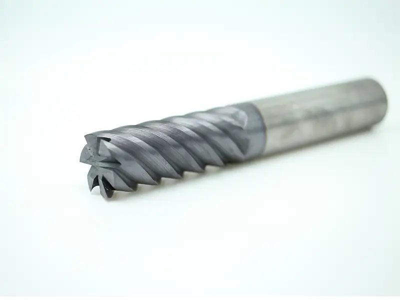
Select flute count for engagement, available chip space, material, and machine capability. More flutes may permit greater table feed at a suitable feed per tooth, but can reduce chip space in slotting or heavy engagement. Variable helix or pitch can help reduce chatter in suitable conditions; it does not eliminate vibration in every setup.
Climb milling is often preferred on a suitably controlled, backlash-compensated machine. At the cutting contact, workpiece feed relative to the cutter is in the same direction as the cutter’s tangential motion; in peripheral milling the chip generally starts thick and becomes thinner. Select the strategy for the setup and surface condition rather than promising universally lower heat or longer end mill life.
Trochoidal Milling
Trochoidal strategies use progressing curved toolpaths to control radial engagement. They may permit greater axial engagement when cutter length, rigidity, and chip evacuation allow. Reduced cycle cost or tool wear must be verified; the entire flute length is not automatically usable.
Carbide Drill Bits for Stainless Steel Drilling
Drilling stainless steel requires attention to chip evacuation, coolant delivery, alignment, and cutting conditions. The appropriate method depends on the hole diameter and depth, drill design, and material condition; drilling is not necessarily the most difficult operation in every job.
HSS and Carbide Drill Selection
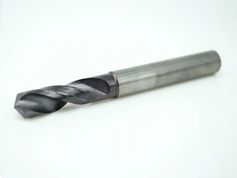
Suitable HSS and cobalt-alloyed HSS drills can machine stainless steel; melting is not a normal defining failure mode. Carbide drills offer greater stiffness and productive capability in appropriate setups, but require suitable alignment, support, and cutting data. Diagnose wear, overload, or chip packing before selecting a replacement.
Drill Geometry
Select drill point geometry, web thinning, flute design, and grade for the stainless material, hole size, and depth. Point angle alone does not guarantee self-centering, and a thicker web can increase thrust unless the geometry is properly designed. Follow the tool supplier’s entry and cutting recommendations.
Through-Coolant Drill Bits
For drilling deep holes, through-coolant tooling can improve delivery to the cutting zone and chip removal when used with the specified pressure and flow. Requirements depend on drill design and hole depth; use the supplier’s complete process rather than assuming every other method must fail.
Cutting Tool Strategy by Machining Operation
Every operation needs a slightly different focus to be successful.
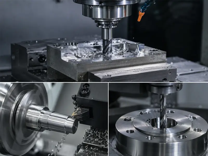
CNC Turning
For turning, select a chipbreaker whose recommended feed and depth-of-cut range matches the operation and material. If chips remain long or entangled, review geometry, engagement, cutting data, and coolant delivery within the tool and setup limits. Do not increase feed indiscriminately, and stop the machine before clearing accumulated chips.
CNC Milling
Avoid unnecessary dwell and rubbing while cutting stainless steel. The extent of work hardening depends on grade, contact, and cutting conditions; it is not an instantaneous outcome of every pause. Use appropriate entry, exit, and chip-load control.
Drilling and Hole Making
Select continuous drilling or a peck cycle according to the drill design, hole depth, material, and coolant delivery. Retraction does not inherently harden the hole bottom. If pecking is specified, use the recommended clearance and re-entry motion; do not force the drill back into the cut.
Speeds, Feeds, and Depth of Cut Reference
Obtain starting parameters from the supplier for the actual tool, material condition, diameter, and operation. Monitor load, wear, chip control, and measured part quality during controlled adjustments; sound alone is not a sufficient setup criterion.
Cutting Speed (Surface Feet per Minute)
For turning 304 or 316, select surface speed from the chosen grade’s application data. Diagnose the wear mechanism and setup before changing speed; a single SFM range cannot cover all inserts and operations.
Feed Rate
For milling, select feed per tooth for cutter diameter, cutting-edge geometry, material, and radial engagement. Apply chip-thinning corrections where appropriate using the supplier’s method rather than a universal inches-per-tooth range.
Depth of Cut
Select roughing and finishing depths within the tool’s engagement range and the limits of the machine and workholding. Avoid rubbing with a suitable chip thickness and edge geometry. There is no universal minimum finishing depth for every tool and stainless grade.
Coolant and Lubrication for Stainless Steel Tooling
Choose coolant or dry machining according to the operation, tool grade, material, and supplier guidance. Turning, drilling, and intermittent milling can require different thermal and chip-control strategies.
Flood vs High-Pressure Coolant
Directed high-pressure coolant can improve chip control in suitable operations, but pressure, flow, nozzle placement, filtration, and equipment ratings must match the tooling. More pressure is not universally better, and a fixed 1000 PSI threshold is not a general requirement.
Dry Machining Risks
Dry machining is appropriate for some qualified stainless-steel milling applications, while many turning and drilling processes benefit from suitable coolant delivery. Follow the tool supplier’s strategy and avoid uncontrolled thermal cycling; carbide is not guaranteed to fail within seconds without coolant.
Tool Wear Patterns and What They Tell You
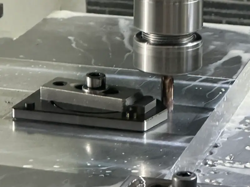
Wear patterns provide clues for diagnosis, but similar damage can have different causes. Inspect the tool together with cutting data, chip formation, cooling, and setup condition before choosing a corrective action.
Built-Up Edge
Built-up edge is material adhering to the cutting edge. Review cutting speed, edge condition, geometry, coating, and lubrication; increasing speed may help in some cases but is not a universal remedy.
Flank Wear
Flank wear is a common wear mode. If it progresses too quickly, assess cutting speed, grade, abrasion, edge loading, and cooling rather than attributing it to speed alone.
Chipping
Chipping can arise from unstable engagement, overload, chip recutting, thermal cycling, or an unsuitable edge preparation or grade. Diagnose the cause and adjust the process; a tougher grade alone may not solve it.
Notch Wear
Notch wear often develops near the depth-of-cut line and can involve work-hardened material, abrasion, or chemical effects. Changing engagement may redistribute wear where the geometry permits, but also check grade, edge preparation, and cutting conditions.
Surface Finishing After CNC Machining
Post-processing is required only when the drawing or service requirements call for it. Select nose radius and feed together with stability and geometry to achieve the specified finish; a larger radius and lower feed are not always better. Passivation or electropolishing addresses separate surface and corrosion requirements and is not automatically needed after every machining operation.
Summary
Successful stainless-steel machining requires tooling and cutting conditions suited to the grade, material condition, operation, and setup. Control chip formation, wear, and thermal effects, use the specified coolant strategy, and verify the resulting dimensions and surface quality.
FAQs
What carbide insert grade is best for 316 stainless steel?
Choose a supplier-recommended grade and chipbreaker for 316, the operation, and the stability of the setup. Both PVD and CVD options may be suitable. Molybdenum content alone does not determine coating choice or guarantee resistance to chipping.
How many flutes should a carbide end mill have for stainless steel?
Flute count depends on cutter diameter, engagement, chip space, and machine capability. Four, five, or more flutes can suit different strategies; compare tool recommendations rather than treating five flutes as universally better.
Why do my carbide drill bits keep breaking in stainless steel?
Check chip evacuation, coolant delivery where required, feed and speed, runout, alignment, workholding, and drill condition. Through-coolant may help where specified, but it does not correct every cause of drill breakage.
Can I use the same carbide inserts for 304 and duplex stainless?
Some grades and geometries cover both 304 and selected duplex stainless steels, but confirm the supplier’s material range and use separate cutting recommendations. Material condition and operation determine speed and achievable life; changing speed alone may not be sufficient.
What is the best coating for carbide tooling on stainless steel?
There is no universal best coating for stainless steel. Select the complete grade, including substrate, coating, and edge preparation, for turning, milling, or drilling and the actual material. Do not infer performance solely from an AlTiN or TiAlN label.