



Fresas de 4 filos: avances y velocidades partiendo del montaje
Ajustar avances y velocidades de una fresa de 4 filos no empieza por unas RPM y un avance únicos correctos. El punto de partida depende de la fresa concreta, material y operación. Con esos datos, el cálculo es sencillo: calcular la velocidad de husillo, multiplicar las RPM por cuatro filos y por el avance por diente elegido, y comprobar si corte y máquina admiten el resultado.
La última comprobación importa. Cuatro filos cortan cuatro veces por revolución, pero dejan menos espacio que una fresa similar con menos filos. El cálculo puede ser correcto mientras el proceso atasca viruta en una ranura, roza en un acabado demasiado suave o sobrecarga un montaje largo y flexible.
Confirmar los datos específicos de la herramienta
Empiece por los datos de la herramienta real. Una tabla general puede explicar variables, pero no considerar sustrato, recubrimiento, preparación del filo, canales o longitud útil. El fabricante suele dar un rango de velocidad de corte y avance por diente para materiales y condiciones definidos. Son una ventana inicial, no una norma aplicable a toda fresa de cuatro filos.
| Valor | Obtener de | Qué controla |
|---|---|---|
Diámetro de fresa, D | Herramienta real o plano | Convierte velocidad de corte en RPM |
Velocidad de corte, Vc o SFM | Datos de herramienta y material concretos | Velocidad inicial de husillo |
Avance por diente, fz o IPT | Datos exactos, incluidas condiciones de contacto | Espesor de viruta previsto antes de corregir por contacto |
Número de filos, z | Fresa real | Cuatro para este cálculo |
| Contacto radial y axial | Operación CAM y trayectoria verificada | Espacio para viruta, carga, flexión y calor |
| Límites de RPM, avance y potencia de máquina | Documentación de máquina y montaje actual | Si puede ejecutarse la orden calculada |
| Descentramiento, voladizo y estado del portaherramientas | Medición e inspección del montaje | Si los cuatro filos comparten el corte |
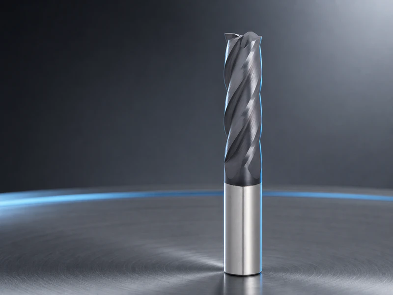
La serie S650 de fresas de cuatro filos para alta dureza permite identificar familias candidatas. No sustituye la comprobación de geometría, tamaño y datos de aplicación antes de programar.
Para comparar productos de uso general, consulte la serie S550 de fresas generales de cuatro filos y confirme después diámetro, geometría y aplicación antes de transferir valores iniciales.
Para comparar más geometrías antes de elegir una serie de cuatro filos, use la página «Fresas de metal duro» y vuelva después a los datos de la herramienta concreta para el cálculo final.
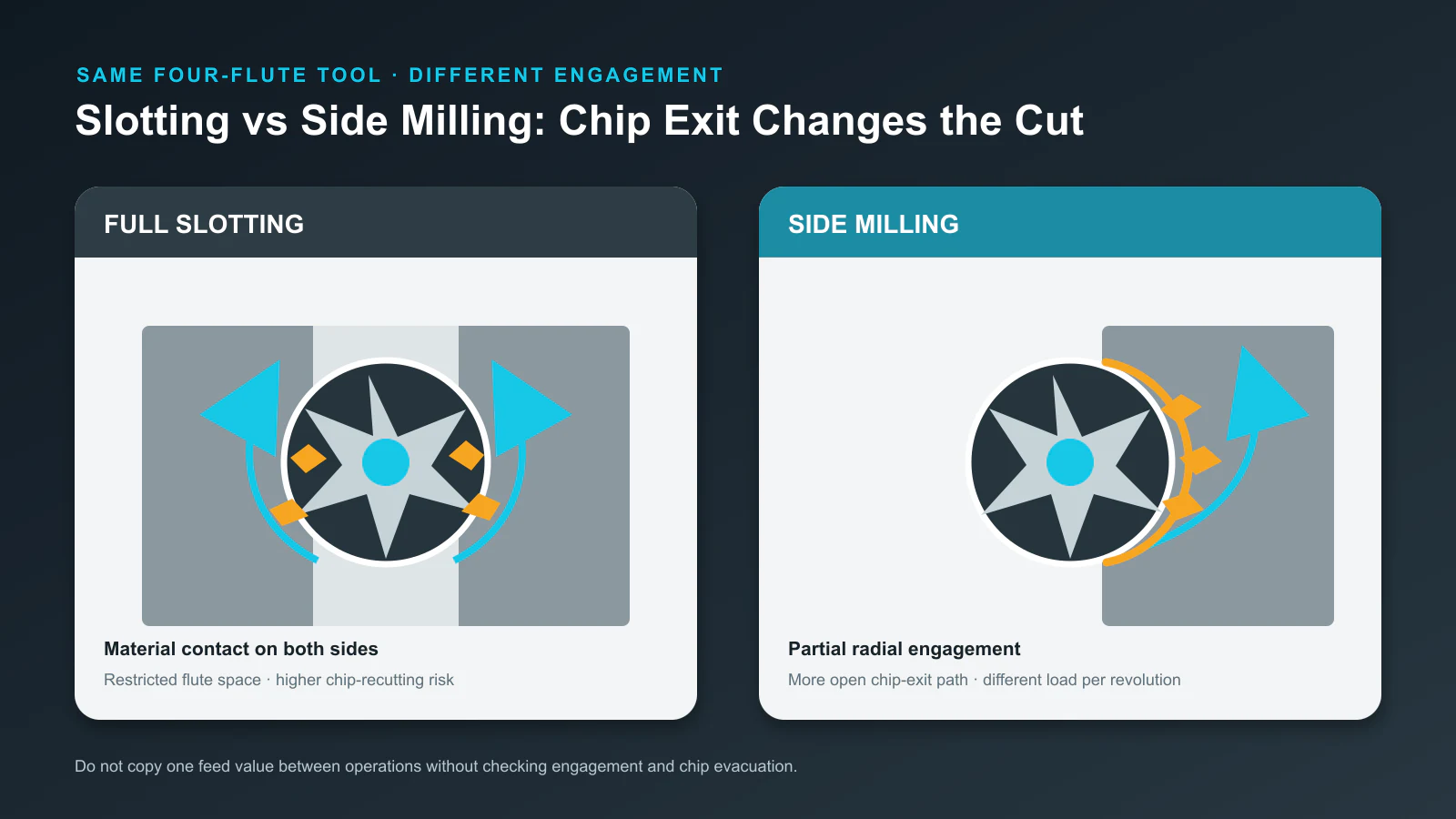
Defina también la operación. El ranurado completo rodea más la fresa y dificulta la salida frente a un corte lateral ligero. Un acabado con poco contacto radial plantea otro espesor de viruta. La misma fresa nominal necesita condiciones iniciales distintas.
Calcular primero RPM y después avance de mesa
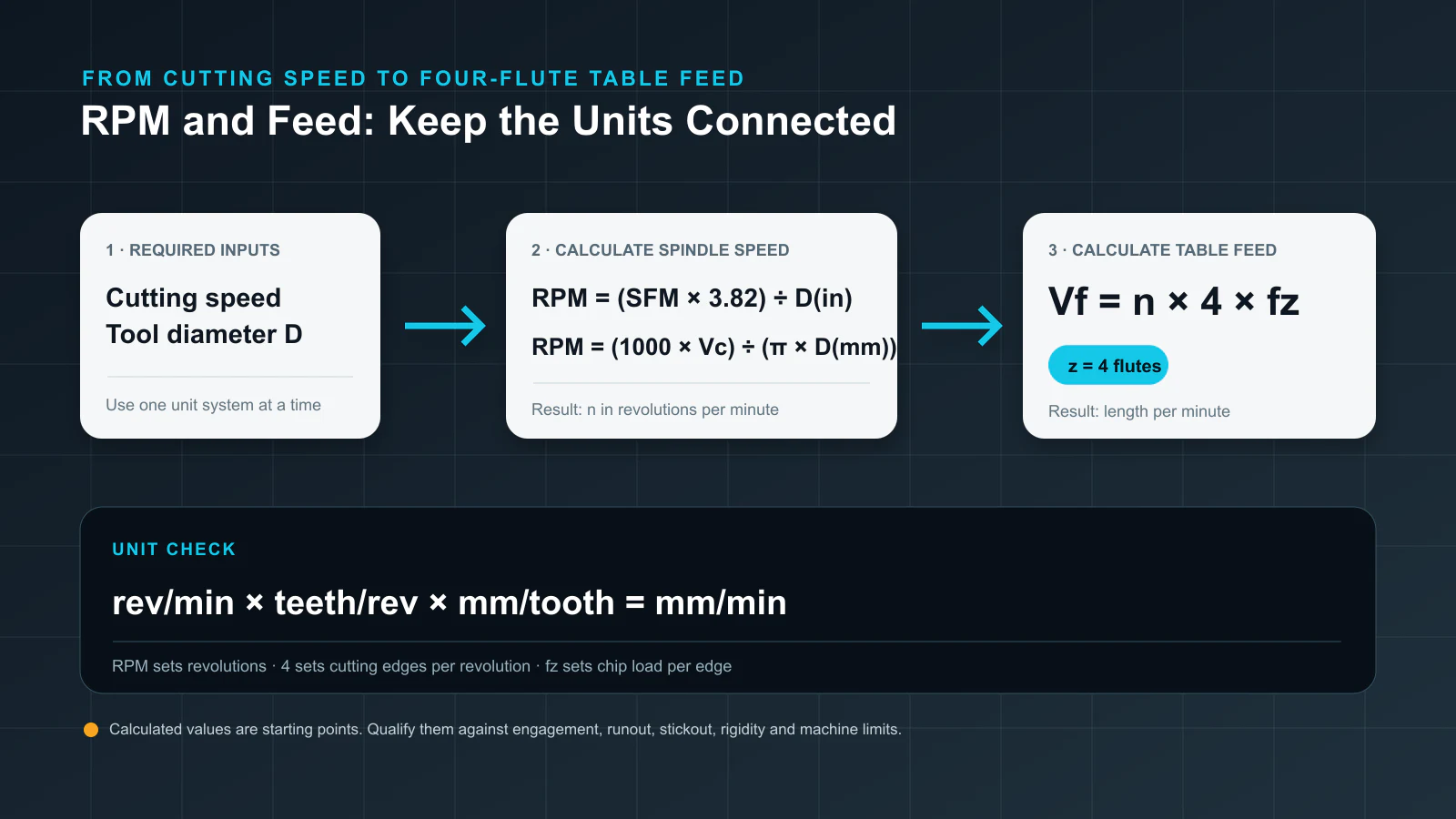
En pulgadas, la velocidad de husillo puede calcularse desde la velocidad superficial en pies por minuto:
RPM = (SFM × 3.82) ÷ D(in)
Para unidades métricas:
RPM = (1000 × Vc) ÷ (π × D(mm))
Use una velocidad de los datos de la herramienta en condiciones equivalentes de material y operación. Compruebe el rango útil del husillo. Si las RPM calculadas superan el límite, use las RPM alcanzables y recalcule el avance de mesa. No mantenga la orden de avance sin cambios.
El avance de mesa es:
Vf = n × z × fz
donde:
Vfes el avance de mesa en pulgadas o milímetros por minuto;nes la velocidad del husillo en revoluciones por minuto;zes el número de filos, aquí 4;fzes el avance por diente en pulgadas o milímetros por diente.
Las unidades permiten comprobar errores rápidamente:
(rev/min) × (dientes/rev) × (longitud/diente) = longitud/min
Si cambian las RPM y se pretende mantener el avance por diente, el avance de mesa debe variar proporcionalmente. Reducir las RPM a la mitad con las mismas IPM duplica el avance por diente. Reducir el avance a la mitad con las mismas RPM puede dejar el filo sin carga suficiente y generar rozamiento. Ambos cambios pueden justificarse al diagnosticar, pero deben ser deliberados.
Cuatro filos explican por qué no puede copiarse sin cambios el avance de dos. A iguales RPM y avance por diente, cuatro requieren el doble de avance de mesa. El cálculo no demuestra que evacúe el doble de viruta. Contacto y espacio siguen limitando.
Validar el valor frente al corte
La fórmula describe el contacto de dientes, no toda la ventana de proceso. Antes de ejecutar las órdenes, contrástelas con estas condiciones.
Ranurado frente a fresado lateral
En una ranura completa, cada filo pasa más tiempo cortando y la viruta debe salir por espacio limitado. Cuatro filos pueden funcionar con material y diseño adecuados, pero una ranura que recorta viruta o retiene calor exige otras condiciones que el fresado lateral abierto.
Con poco contacto radial, el espesor de viruta puede ser menor que el sugerido por el avance por diente. Es el adelgazamiento radial de viruta, un cálculo separado que depende del diámetro y contacto radial. No compense con un porcentaje sin explicar. Use las indicaciones del fabricante o un cálculo de adelgazamiento validado para esa trayectoria.
Descentramiento y carga de filos
El avance por diente supone reparto del trabajo. El descentramiento puede cargar más un filo mientras otro apenas corta. Cuatro filos se comportan entonces como uno o dos sobrecargados. Inspeccione portaherramientas, pinza, cono y herramienta, y mida el descentramiento en procesos sensibles o si fallos repetidos sugieren carga desigual.

Voladizo, portaherramientas y respuesta de máquina
Más voladizo eleva el riesgo de flexión. La flexibilidad de herramienta, portaherramientas, pieza o máquina puede convertir una carga razonable en vibraciones, conicidad o mal acabado de pared. El límite de RPM no es el único: importan potencia disponible y avance alcanzable.
La respuesta correcta no siempre es reducir todo. El rozamiento puede requerir más espesor de viruta. La vibración puede necesitar menos contacto radial, menor voladizo, mejor apoyo o distinta zona de velocidad. Identifique la limitación antes de editar el programa.
Probar el ajuste sin cambiar todo a la vez
Trate el primer corte como una prueba controlada.
- Confirme identidad, diámetro, filos, longitud útil y estado.
- Verifique limpieza, sujeción, voladizo, fijación de pieza y trayectoria.
- Registre la fuente de velocidad y avance por diente y sus condiciones de contacto.
- Calcule RPM y avance de mesa. Compruebe unidades y límites.
- Empiece con contacto conservador o condición de prueba aprobada. Mantenga la relación prevista de avance por diente salvo que se esté probando el espesor de viruta.
- Observe carga y evacuación. Escuche un corte estable y compruebe que la viruta sale sin recortarse.
- Pare si se atasca viruta, el sonido se vuelve inestable, aumenta bruscamente la carga, hay calor anormal o la pieza empieza a moverse o flexionar.
- Inspeccione viruta, filo, acabado de pared o fondo y dimensiones antes de aumentar la exigencia.
- Cambie una variable y registre el resultado.
Los ajustes de avance y velocidad ayudan durante la prueba, pero pueden ocultar la relación RPM–avance. Si cambian ambos, registre los valores efectivos y calcule el avance por diente antes de aceptarlos como nuevo programa.
Interpretar la señal de fallo antes de corregir
| Señal | Verificar primero | Primera dirección de ajuste |
|---|---|---|
| Polvo fino, embadurnamiento, mala formación del filo o pulido rápido | Avance por diente real, descentramiento y aumento de RPM sin avance | Restablecer la carga prevista dentro de límites; no reducir automáticamente el avance |
| Viruta acumulada, marcas de recorte o calor creciente | Aire o refrigerante, espacio, contacto radial y salida de viruta | Mejorar evacuación o reducir contacto; reconsiderar si los cuatro filos sirven para esa ranura |
| Carga alta, flexión, conicidad o astillado | Identidad, material, contacto, voladizo, portaherramientas y potencia | Reducir una condición de carga cada vez; acortar o rigidizar cuando sea posible |
| Marcas repetidas de vibración o sonido inestable | Descentramiento, portaherramientas, fijación, frecuencia natural y velocidad | Corregir primero holguras mecánicas y probar después un cambio deliberado de velocidad o contacto |
| Un filo se desgasta o astilla antes que los demás | Descentramiento, filo, pinza y asiento de herramienta | Corregir el reparto de carga antes de reducir todo |
La temperatura sola no completa el diagnóstico. El calor puede proceder de rozamiento, velocidad excesiva, recorte de viruta o mala refrigeración. La corrección difiere en cada caso.
Comprobación de puesta en marcha
Antes de validar, el registro debe responder estas preguntas:
- ¿La fuente de velocidad y avance por diente corresponde a la herramienta y material concretos?
- ¿Las RPM, cuatro filos y avance programados reproducen el avance por diente previsto?
- ¿Se indican contacto radial y axial?
- ¿Puede salir la viruta sin recortarse?
- ¿Son adecuados descentramiento, voladizo, portaherramientas y fijación?
- ¿La máquina alcanza RPM y avance programados en la trayectoria real?
- ¿La prueba produjo sonido estable, carga manejable, filos intactos y pieza aceptable?
- ¿Cada ajuste tenía un motivo registrado?
Si falta alguna respuesta, el proceso sigue en validación. Tabla o calculadora dan el primer valor; máquina, viruta y pieza medida determinan si debe usarse en producción.