


A Complete Guide to Boring Tools: How They Work and When to Use Them
Precision hole machining can involve drilling, reaming, and boring. Boring can be among the toughest operations when access, overhang, or tolerance requirements are demanding; it is not universally harder than every other process.
Boring tools include single-edge and multi-edge designs. Some fine-boring heads allow micrometer-level adjustment. H7 and H6 designate hole tolerance zones whose widths depend on nominal size; neither is a fixed accuracy guaranteed by adjusting one edge.
A qualified boring process can improve hole dimensions and surface finish. Surface quality must be specified and measured; a finish smoother than a gauge block is not a general capability. This guide explains tool selection and application.
Contents
What Are Boring Tools?
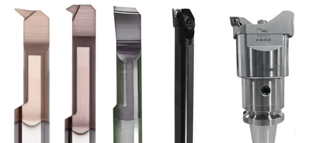
Ever needed to fine-tune a hole’s size or finish in metalworking? That’s where boring tools come in—your go-to for precision hole work. Think of them as specialized cutters designed to enlarge, refine, or shape existing holes with killer accuracy. They’re not making new holes; they’re perfecting ones you already got.
You’ll usually find one or two cutting edges on these tools (that’s the part doing the hard work). Whether you’re roughing out material, doing a semi-finish pass, or putting on that final mirror-like finish, there’s a boring tool for the job. And hey, don’t sweat the setup—you can run ’em on your lathe, milling machine, or a dedicated boring setup.
Got a hole that’s slightly off-size or rough inside? Grab a boring bar or tool. It’s like giving that hole a second chance to shine.
Common Types of Boring Tools
Single Flute Boring Tool
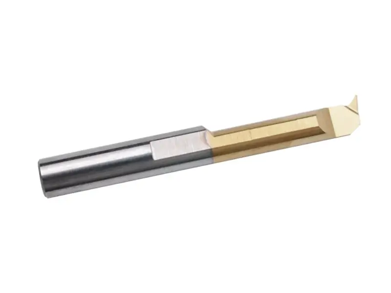
A single-edge boring tool uses one cutting edge to enlarge an existing hole. Some fine-boring heads allow diameter adjustment while the tool remains mounted, with the spindle stopped and the machine secured.
Some heads use a fine adjustment mechanism, but not every single-edge tool has a dial. A stated 0.001 mm increment may describe an adjustment resolution, not achieved hole accuracy; check whether it is radial or diametral. Make adjustments only with the spindle stopped and follow the manufacturer’s procedure for you and your machine.
Adjustable Double-Edge Boring Tools
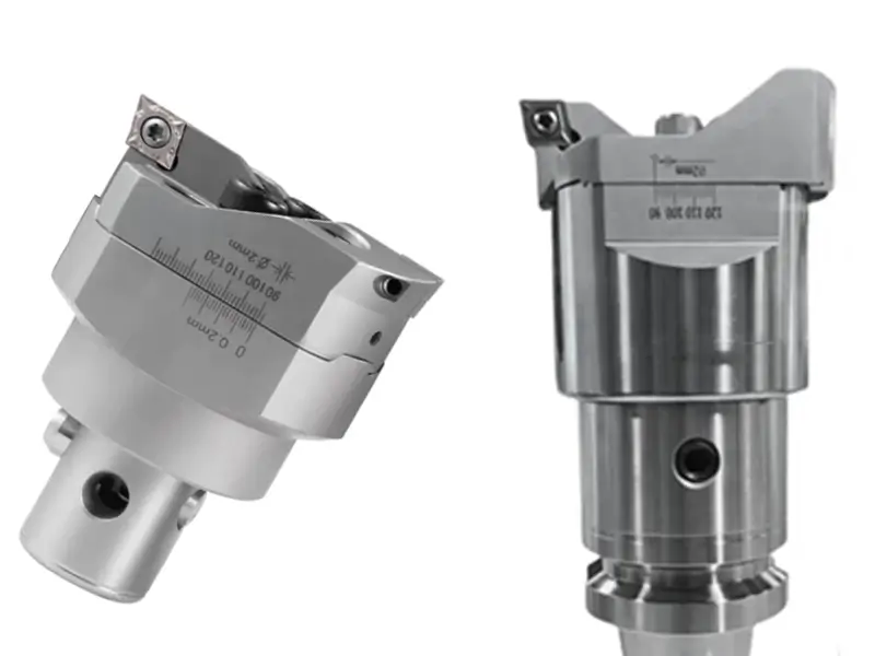
Boring tools with two cutting edges can support productive machining. Opposed edges may reduce net radial loading when correctly set, but forces do not automatically cancel, and vibration or finish improvement is not guaranteed.
Now, here’s where it splits:
- Floating Boring Tools: A floating design may accommodate limited alignment variation in a suitable application. It does not replace accurate setup or guarantee the specified size, geometry, and finish.
- Fixed Boring Tools: Rigid setup. You lock ’em dead-center. Best when your setup’s already dialed-in rock-solid and you need pure stability.
How to Choose the Right Boring Tool
Tool Rotation
On a machining centre, the tool spins. Select the boring head for the required diameter, tolerance, balance, and speed. Fine adjustment or automatic compensation is available on some designs but is not necessary for every boring operation.
Tool rotation, bore orientation, coolant delivery, and chip geometry affect chip evacuation. A rotating tool is not inherently harder to cool or evacuate than a stationary boring bar in every application.
Tool Vibration
Vibration kills finish and accuracy. Here’s what cranks it up:
- System Rigidity: Flimsy tool holders, skinny boring bars, or weak connectors? Disaster for small holes, deep bores, or hard materials—especially in overhang setups. Stiffness is non-negotiable.
- Dynamic Balance: If the tool’s mass ain’t even around its spin axis? Centrifugal force shakes it like crazy at high RPM. Balance matters most when you’re pushing speed.
- Workpiece Rigidity: Thin walls or weak clamping can cause deflection and chatter. Suitable fixtures and supports can improve stiffness, but must avoid distorting the workpiece.
- Blade Geometry: That cutting edge’s rake angle, tip radius, and chip breaker design change cutting forces—and vibration.
- Cutting Conditions: Speed, feed, depth of cut, and coolant flow all play in. Push too hard? It’ll sing.
- Spindle Health: Worn bearings, loose tool holder fit, or a sloppy spindle? Your vibration starts here.
Properly Clamp the Tool
Clamping and centre height must follow the tool and machine instructions. A wrong setting can change effective geometry and cause rubbing or poor cutting.
- Too low: Depending on tool orientation and bore geometry, an incorrect centre height can reduce clearance or alter engagement. It does not universally pull the tip deeper.
- Too high: An excessive centre-height error can impair clearance and size control. Its effect depends on the mounted tool and cutting direction.
Just use the centre-height setting specified for the particular holder and operation. Do not apply an above-centre offset universally. Deflection
down or in another direction depends on loading and mounting; it is not a collision-protection mechanism.
A positive cutting geometry can reduce forces in suitable boring applications, but edge strength must also be considered. Neutral or negative geometry does not automatically cause breakage; select the insert and holder together.
Diameter and Length
Your boring bar’s size lives and dies by the hole’s diameter and depth. Rules of thumb:
- Shortest overhang possible.
- Largest bar diameter that fits (leave chip-clearance space!).
- Follow the holder supplier’s required clamping length; ≥ 3x bar diameter is not a universal minimum for every boring bar and interface.
Why rigidity rules:
Tangential and radial forces will try bending your bar. Any bend means:
→ Uneven cutting depth → vibration.
→ Hole size errors.
→ Blade drifting off-centerline.
Blade selection hacks:
- Use an appropriate entering angle, often near 90° in conventional internal turning, to influence force direction into the axial direction. The original >75° advice concerns entering angle, not clearance angle.
- Positive rake inserts = lower cutting forces.
- Select nose radius and depth of cut together to control forces and chip formation. The 0.4 mm radius and 0.5 mm depth example is not a universal setting.
- Sharp edges = cleaner holes, less chatter.
- Open chip-breaker geometry – lets chips flow.
- Choose coating, substrate, and edge preparation for the workpiece. Cermets and uncoated or thin-coated inserts do not reduce cutting forces in every application.
Chip Evacuation is KING:
- Chip shape must suit the operation. Short, controlled chips can aid evacuation; short chips alone do not establish high power consumption, vibration, or notch wear.
- Long chips = birds nests, jammed tools.
- Aim for chip forms that evacuate reliably without packing or damaging the bore; tight helices are not the only acceptable form.
Stop chips wrecking your hole:
- Use approved coolant delivery to reach the cutting zone and carry chips out of the bore. Internal coolant passages normally supply fluid; they are not a general chip-return path through the tool.
- Use only a machine-approved air or coolant system and control chip ejection. Do not direct debris back into the spindle or assume compressed air is permitted for every setup.
- Bore orientation may help chips move away from the cutting zone when the machine, tool, and workholding permit it.
- Check actual clearance and chip-control conditions. Lowering speed does not create geometric clearance, and a smaller head must still meet stiffness and cutting requirements.
- Change tool path if chips keep clogging.
If clogging or chatter persists, stop and diagnose alignment, support, geometry, coolant, and cutting data. A tougher grade alone does not remedy every unstable or blocked process.
Tired of fighting chatter or chasing microns? When off-the-shelf boring tools just won’t cut it for your job—maybe it’s a weird size, brutal material, or insane tolerance—Sundi’s got your back.
We don’t just sell tools; we build solutions. Send us your prints, and we’ll engineer custom boring bars and tooling that fit your hole, your machine, and your deadlines. Got a nightmare alloy or a deep-hole puzzle? Bring it.
Don’t compromise your finish. [Contact Sundi Today] – let’s make your toughest holes your easiest jobs.