Skip to content
Cylinder Head Machining Tools for Resurfacing, Valve Jobs, and CNC Porting
Cylinder head machining is not only a repair operation. For engine shops, OEM machining teams, and tool buyers, the harder question is which cutting tools can control deck finish, valve seat concentricity, guide clearance, and CNC porting repeatability without creating new sealing or reliability problems.
This guide looks at cylinder head machining from the tooling side. It maps resurfacing, valve seat machining, valve guide reaming, and CNC porting to practical cutter choices such as PCD face milling cutters, PCBN / CBN turning inserts, carbide form end mills and profile cutters, carbide reamers, and PCD reamers.
Cylinder head machining tools by operation
Cylinder head machining usually includes some combination of deck resurfacing, valve seat cutting, valve guide sizing, CNC porting, cleaning, inspection, and measurement. The exact operation decides the tool: a clean deck finish is a different cutting problem from a concentric valve seat, a controlled guide bore, or a repeatable porting path.
The useful way to think about cylinder head work is not only “what machine touched it?” but “what feature is being controlled, and what cutter geometry can control it repeatedly?”
| Operation | Feature being controlled | Tooling focus | Sundi product direction |
|---|---|---|---|
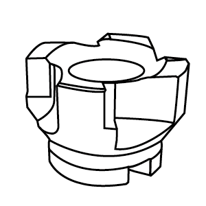
| Deck resurfacing | Flatness, surface finish, waviness | Stable face milling, sharp edge, controlled finish pattern | PCD indexable face milling cutter for aluminum and nonferrous head work |
| Valve seat machining | Seat angle, concentricity, contact width, finish | Rigid cutting edge, stable insert grade, chatter control | PCBN / CBN turning inserts for hard seat materials and cast iron applications |
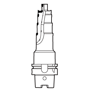
| Valve guide machining | Guide bore size, alignment, stem clearance, finish | Reamer stiffness, wear resistance, alignment, hole finish | Carbide reamer or PCD reamer depending on guide material and finish target |
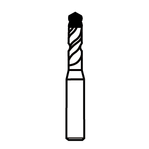
| CNC porting | Airflow path, cross-section, transition shape | Profile access, edge stability, repeatable toolpath contact | Carbide form end mills and profile cutters for contour and porting features |
| Special engine features | Custom profiles, difficult access, combined operations | Custom geometry, tool life, process repeatability | Custom PCD / CBN special tools for high-value engine component production |
These operations are linked. A loose or poorly finished guide can make valve seat cutting unstable because the pilot is not supported. A seat that is not concentric to the guide may look clean but fail a leak test. A freshly surfaced deck may still cause trouble if the head was clamped in a stressed position while cutting. Cylinder heads reward boring discipline: clean setup, rigid tooling, small controlled corrections, and measurement before the next cut.
Deck resurfacing tools: flatness, finish, and gasket sealing
Deck resurfacing is the operation most people notice first because it leaves a visible machined surface. But the goal is not to make the aluminum or cast iron look pretty. The goal is to create a surface that lets the gasket seal under real clamping load, heat, and combustion pressure.
Flatness matters, but surface texture matters too. Modern MLS gaskets are less forgiving of roughness and waviness than many older gasket styles. The deck may pass a casual visual check and still show cutter marks, chatter, or waviness that make sealing unreliable. That is why resurfacing discussions often come back to the same practical worries: was the machine trammed, was the head clamped without distortion, was the cut consistent, and was the finish appropriate for the gasket?
A single-pass fly cut is often preferred when it can remove enough material while leaving a consistent surface. Multiple passes are not automatically wrong, but each pass gives the setup another chance to show weakness. If the head shifts, the machine is not rigid, or the cutter is not dialed in, the surface may show a pattern that is hard to trust.
Clamping is easy to underestimate. A cylinder head is not a solid rectangular block. It has chambers, water jackets, bolt bosses, and thin sections. If the head is forced flat or stressed during setup, the machine may cut a surface that measures differently once the part is released. That is why a shop’s fixture strategy matters as much as the cutter brand.
Material also affects tooling choices. Aluminum cylinder heads are often associated with sharp, wear-resistant tooling that can leave a clean finish without smearing. Cast iron behaves differently and may call for different inserts, speeds, and cutter geometry. The key is not memorizing one universal recipe. It is matching the cutter, machine, feed, and finish target to the material and gasket requirement.
Valve seat machining tools: concentricity, seal, and chatter control
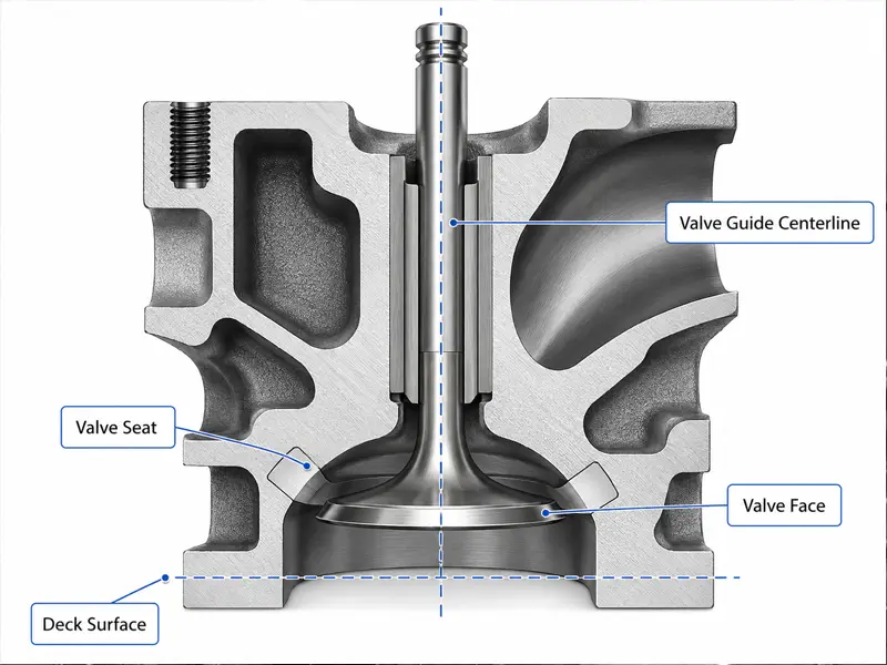
Valve seat machining controls where and how the valve seals against the head. The 45-degree sealing surface is the area most builders watch closely because it directly affects compression and leak performance. Other angles shape flow and transition, but if the main sealing contact is poor, the head has a real problem.
The seat must be concentric to the valve guide. That is why pilot fit and guide condition matter so much. If the pilot does not fit the guide properly, the cutter may not follow the true valve centerline. The result can be a seat that looks machined but does not seal evenly around the valve.
Chatter is one of the classic valve job problems. It may appear as a repeating vibration mark on the seat or adjacent angle. Chatter can come from weak rigidity, poor pilot support, a loose setup, too much cutter contact, hard seat material, poor speed/pressure choices, or inadequate cutting fluid. The fix is rarely “just cut it again” without understanding the cause. Another pass with the same unstable setup can sink the seat farther while keeping the same problem.
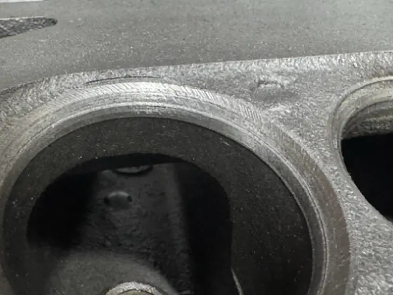
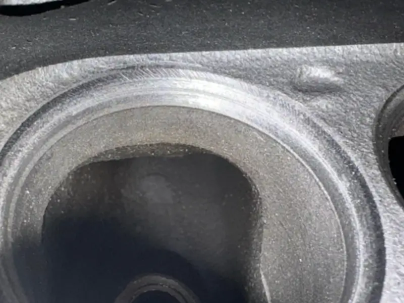
Not all visible marks have the same severity. Chatter on a non-sealing angle may be less critical than chatter on the 45-degree seat, but it still tells the machinist that something in the process is vibrating. Before removing more material, check whether the guide is sized correctly, whether the pilot fits, whether the head is mounted solidly, and whether the cutter is being asked to engage too much surface at once.
The practical goal is controlled contact. A clean seat should show an even contact band in the right location on the valve face. If the seat is sunk too far, contact location and installed height may become bigger problems than the original chatter. Good machining is not just making the surface continuous; it is preserving the geometry the engine needs.
Lapping valves: useful check or false sense of repair?
Valve lapping is often misunderstood because it sits between machining and inspection. After a precise modern valve job, lapping may not be required at all. In some cases, aggressive lapping can actually hide the fact that the seat geometry should have been corrected by cutting.
Light lapping can still be useful. It can confirm contact pattern, clean up small surface irregularities, or help when valves were mixed, handled, or lightly marred. The important word is light. Lapping should not be used as a magic eraser for a seat that is not concentric, a valve face that is damaged, or chatter that belongs back at the machine.
Use the right compound. Metal polish is not valve lapping compound, and the wrong abrasive can waste time or create misleading results. After lapping, the part also needs careful cleaning because abrasive left in the head is not harmless.
There are better ways to turn lapping into evidence. A Sharpie or Dykem contact check can show where the valve touches the seat. A fluid leak check or vacuum test can reveal whether the valve seals. These checks do not replace measurement, but they prevent the common trap of assuming a dull gray ring means the valve job is good.
Valve guide reaming tools and bore control
Valve guide work is where many cylinder head jobs quietly succeed or fail. The guide controls the valve stem, but it also influences the seat machining process because the valve seat pilot references the guide. If the guide is worn, crooked, too tight, poorly finished, or inconsistently sized, the valve job becomes harder to trust.
Hand reaming can work in simple situations, but it is risky when alignment and finish matter. A tap wrench and a loose hand feel may not keep the tool straight enough. The guide can end up bell-mouthed, rough, or tighter than expected after assembly conditions change. This is why experienced builders often talk about piloted reamers, incremental sizing, honing, or ball broaching instead of treating a guide as an ordinary drilled hole.
A carbide reamer can fit guide work when the material and setup support a clean, controlled cut. Carbide brings stiffness and wear resistance, but it still needs alignment, lubrication or cutting strategy, and the right size progression. A good reamer in a poor setup can still produce a bad guide.
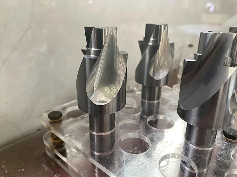
A pcd reamer fits a different part of the tooling conversation. In aluminum or nonferrous precision hole finishing, especially where edge life and surface finish matter, PCD tooling can make sense. In cylinder head work, that may be relevant to parent-metal bores, guide-related holes, or high-repeatability nonferrous finishing. It should not be forced into every guide discussion, and it is not a substitute for knowing the target clearance and checking the final result.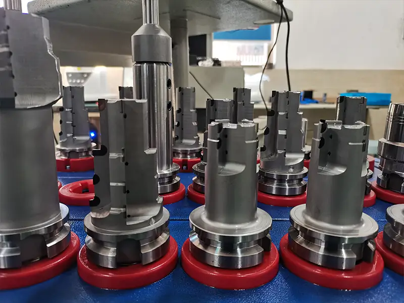
Honing is often preferred when final size and finish are critical. It can correct small sizing issues and produce a more controlled surface than a rough hand-reamed guide. But honing requires equipment and skill. If a guide ends up too tight, the answer may be controlled honing, a ball broach, or another measured sizing step rather than pushing the valve through and hoping it frees up later.
The final checks are simple in concept: correct stem clearance, smooth movement, suitable surface finish, and consistent feel across guides. The process behind those checks is where the skill lives.
CNC porting tools for cylinder head airflow work
Porting is different from repair machining because the goal is not only to restore a surface. The goal is to shape airflow while keeping wall thickness, valve job quality, chamber behavior, and repeatability under control.
Hand porting can be excellent for one-off development when the person doing the work understands the head and the engine combination. The challenge is repeatability. One good port does not automatically become eight, sixteen, or a production batch. If the next port is shaped differently, the engine may not behave consistently.
CNC cylinder head porting turns a successful shape into a repeatable machining process. That usually involves digitizing a known-good port, building or refining CAD/CAM data, creating fixtures that locate the head consistently, and choosing a machine strategy that can reach the required surfaces. Five-axis machining, specialized fixtures, and turn-mill access can all matter depending on port geometry.
The real value of CNC porting is not that it sounds advanced. It is that it can repeat a developed shape with less variation. That repeatability depends on setup and measurement. If the fixture locates differently, if the tool cannot reach the same surface cleanly, or if the model does not match the real casting variation, CNC becomes expensive motion rather than controlled improvement.
For most repair readers, the takeaway is straightforward: porting should be treated separately from resurfacing and valve repair. For performance readers, the better question is not “is it CNC ported?” but “what shape was developed, how was it digitized, how is the head located, and how is repeatability checked?”
Measurement and inspection after machining
Inspection is not a final ceremony. It is feedback that tells the machinist whether the previous operation actually did what it was supposed to do.
After resurfacing, the deck should be checked for flatness and finish quality. A visual surface can be misleading, especially under shop lighting. Cutter marks, waviness, or inconsistent texture can point to setup or tooling issues. For MLS gasket work, the surface requirement is usually tighter, so “looks clean” is not enough.
After valve seat machining, check contact pattern and sealing. A valve that contacts too high, too low, too wide, too narrow, or unevenly may need correction. Leak checks, vacuum checks, and contact marking can all help reveal problems before the head is assembled.
After guide work, check clearance and valve movement. A guide that feels acceptable dry on the bench may behave differently once temperature, oil, and assembly conditions enter the picture. The guide also needs enough consistency to support the seat-cutting pilot.
After porting, inspection depends on the goal. A performance development job may use airflow testing, templates, thickness checks, or comparison against a digitized model. A production CNC porting job needs repeatability checks so the tenth head does not drift away from the first one.
Common cylinder head machining problems people actually worry about
The most useful cylinder head advice often starts with a problem someone is already seeing.
| Symptom | Likely process area | What to check before cutting again |
|---|---|---|
| Head still does not seal after resurfacing | Deck flatness, finish, gasket match, clamping | Flatness, cutter pattern, head stress in fixture, gasket requirement |
| Valve seat chatter | Seat cutter rigidity, pilot fit, guide condition, speed/pressure | Guide size, pilot fit, head mounting, cutter engagement, lubrication |
| Seat looks clean but leaks | Concentricity, contact position, valve face condition | Contact pattern, leak/vacuum test, seat runout, valve face |
| Seat has been cut too deep | Excessive correction passes, wrong setup, trying to remove chatter by cutting | Installed height, contact location, remaining seat geometry |
| Guide is too tight after reaming | Reamer size, finish, alignment, burrs, material spring | Final clearance, honing option, ball broach option, cleaning |
| Lapping shows uneven ring | Seat/valve misalignment, valve mix-up, poor contact | Marking pattern, valve identity, light leak test, seat correction |
| CNC port shape varies | Fixture, casting variation, model/toolpath mismatch | Location strategy, digitized data, process checks, repeatability sample |
This is where the Reddit-style evidence is valuable. Real users do not ask abstract questions. They ask whether a chatter mark ruined the head, whether lapping is necessary, whether a hand reamer made the guide too tight, or why a resurfaced head still looks wrong. Those questions are useful because they point to the quality controls the article must explain.
When cylinder head machining needs custom cutting tools
Some cylinder head jobs can run with standard cutters and careful setup. Custom cutting tools become more useful when the head design repeats in production, when the valve seat or guide geometry is hard to hold, when a porting path needs repeatable access, or when cycle time and inspection data show that general-purpose tooling is not stable enough.
The decision should come from the operation, not from tool preference alone. A resurfacing job may need a dedicated PCD face milling cutter. A hard seat ring may justify CBN or PCBN tooling. A valve guide operation may need a carbide or PCD reamer with the right lead, diameter control, and finish behavior. A porting feature may need a profile cutter that can reach the shape without rubbing or chatter.
For production engine components, the best custom tool is the one that reduces variation. It should make the cut easier to measure, easier to repeat, and easier to connect with the next inspection step.
Cylinder head machining checklist before cutting
Use this checklist before cutting, quoting, or approving a cylinder head job.
| Checkpoint | Why it matters |
|---|---|
| Identify head material and gasket type | Material and gasket style affect surface finish and tooling choices |
| Check for cracks, warpage, and previous machining | A damaged head may not be worth further cutting |
| Define the actual operation needed | Resurfacing, valve job, guide work, and porting are different jobs |
| Confirm fixturing and clamping strategy | A stressed head can cut wrong even on a good machine |
| Measure or correct guides before seat work | Seat machining references the guide centerline |
| Choose reaming/honing method based on guide material and finish requirement | Tool choice affects size, finish, and valve movement |
| Verify valve seat contact before assembly | A clean-looking seat can still seal poorly |
| Treat lapping as verification or minor cleanup | Lapping should not replace proper seat correction |
| Document porting process if repeatability matters | CNC repeatability depends on digitizing, fixture, and process control |
| Inspect after each major operation | Early feedback prevents repeated material removal |
Conclusion
Cylinder head machining is a process-control job. The visible cut is only one part of the result. A reliable head depends on flatness, finish, guide alignment, seat geometry, valve contact, fixturing, and inspection all working together.
The best approach is to start with the problem the head actually has. Do not resurface just because the deck looks dull. Do not keep cutting a chattering valve seat without fixing rigidity or pilot support. Do not rely on lapping to correct bad geometry. Do not treat a carbide reamer, PCD reamer, or CNC program as a shortcut around measurement.
When the setup, tooling, and inspection match the job, cylinder head machining can restore sealing, improve reliability, and make performance work repeatable. When they do not, every extra cut simply removes more of a head that may have been saveable.
FAQ
What is included in cylinder head machining?
Cylinder head machining can include cleaning, inspection, deck resurfacing, valve seat machining, valve guide sizing, valve lapping or verification, chamber work, porting, and final measurement. The exact operations depend on the head condition and the engine goal.
Does every cylinder head need resurfacing?
No. A cylinder head should be inspected first. Resurfacing is useful when flatness, surface finish, corrosion, gasket failure, or previous damage requires correction. Cutting a head unnecessarily can remove material and change geometry without solving a real problem.
Is valve lapping required after cutting seats?
Not always. A precise valve job may not need lapping. Light lapping can help verify contact or clean up minor surface issues, but it should not be used to fix poor seat geometry, chatter, or concentricity problems.
What causes chatter in a valve job?
Valve seat chatter is usually a rigidity or process-control problem. Common contributors include poor pilot fit, worn or incorrectly sized guides, weak head mounting, hard seat material, too much cutter contact, and unsuitable speed, pressure, or lubrication.
What tool is used for valve guide reaming?
Valve guides may be sized with piloted reamers, carbide reamers, adjustable or fixed reamers, honing tools, or ball broaches depending on the material, equipment, and target finish. The tool must be aligned and followed by a real clearance check.
When are PCD or carbide reamers used in cylinder head work?
A carbide reamer may be used where stiffness and wear resistance help produce a controlled guide or bore finish. A PCD reamer is more likely to fit aluminum or other nonferrous precision hole-finishing work where edge life and surface finish matter. Neither tool replaces fixturing, alignment, and measurement.
What tools are used for cylinder head resurfacing?
Cylinder head resurfacing often uses a face milling cutter or dedicated resurfacing cutter selected for the head material, gasket finish requirement, and machine rigidity. Aluminum heads may benefit from sharp PCD tooling, while cast iron may call for a different insert grade and cutting condition.
When are CBN tools used for valve seat machining?
CBN or PCBN tooling can be useful when valve seat material is hard or abrasive enough that ordinary carbide loses stability, finish, or tool life. The final choice depends on seat material, contact geometry, rigidity, speed, and the required surface condition.
When should cylinder head machining be outsourced?
Outsource the job when the operation requires surface-finish control, valve seat concentricity, guide sizing accuracy, crack/pressure testing, or repeatable CNC porting beyond your equipment. A specialist shop is often cheaper than correcting a head that was cut without the right setup.