Skip to content
Drill Point Angle Chart: 118° vs 135° by Material and Application
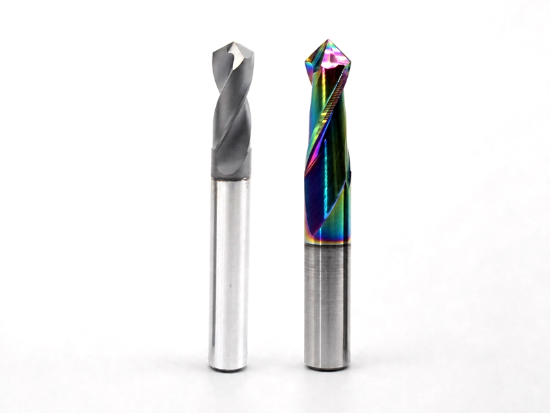
A drill point angle chart is useful for narrowing the field, but it cannot select a drill by itself. A 118° point is a familiar general-purpose starting point. A 135° point is flatter and shortens the point height, and it is often offered with split-point geometry. Neither angle is universally correct for a material.
Use the chart below as a first filter. Then verify the complete drill geometry, workpiece grade, diameter, hole depth, setup rigidity, coolant delivery, and chip-evacuation requirements against the tool manufacturer’s data.
Quick Drill Point Angle Chart
This drill point angle for different materials is deliberately conditional. Material names alone are too broad to function as a finished specification.
| Material or application | Useful starting point | Why it may help | Verify before cutting |
|---|---|---|---|
| General-purpose low- and medium-carbon steels | 118° general-purpose geometry, or a tool-specific 135° option | Both are common; the complete point design and setup decide the result | Steel grade, drill construction, diameter, depth, rigidity, coolant |
| Stainless steels and other work-hardening alloys | Use the point geometry specified for the exact drill and alloy | Edge strength, heat control, and continuous chip formation matter more than a two-angle rule | Alloy, tool material/coating, feed continuity, coolant, peck strategy |
| Cast irons | Start with the drill maker’s cast-iron recommendation | Abrasiveness and the form of the chips vary by iron grade | Iron grade, tool material, dust/chip control, hole tolerance |
| Aluminum and other nonferrous alloys | Use geometry designed for the alloy and chip volume | Rake, flute finish, and evacuation can dominate the angle choice | Alloy, loading tendency, through-tool coolant, flute capacity |
| Thin sections or entry-sensitive work | Consider a flatter point or an appropriate split-point design | A shorter point and lower thrust at entry may be useful in the right construction | Work support, breakthrough behavior, burr requirement, documented tool guidance |
| Hardened or high-strength workpieces | Follow a drill-specific application chart | “Hard material = 135°” is not enough to define edge preparation or tool material | Actual hardness, tool substrate/coating, machine rigidity, coolant, depth |
The chart is a shortlist, not permission to ignore the drill maker’s speed, feed, coolant, and application limits.
118° vs 135°: What the Angle Actually Changes
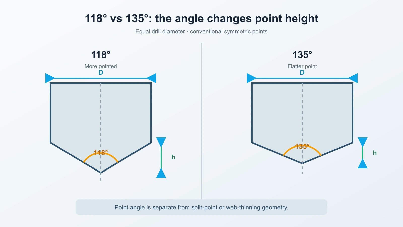
The included angle changes the shape and axial length of the point. A 118° point is more pointed; a 135° point is flatter.
| Decision factor | 118° point | 135° point |
|---|---|---|
| Point shape | More pointed | Flatter |
| Conventional point height | About 0.300 × diameter | About 0.207 × diameter |
| Common positioning | Familiar general-purpose baseline | Common flatter option in application-specific drills |
The phrase 118 degree drill point describes the included angle, not the tool material, web thickness, edge preparation, helix, flute finish, or coating. The same is true of a 135 degree drill point. Those omitted details can determine cutting behavior, so an angle-only comparison has a hard limit.
Point Angle and Split Point Are Separate Decisions
At the center of a conventional twist drill, the chisel edge tends to push material before the cutting lips take over. Web thinning and split-point grinding modify that central region. They can reduce thrust and improve starting behavior, but they are not encoded by the included angle.
That distinction prevents a common buying mistake: a split point drill is defined by its center geometry, not simply by a 135° label. Some 135° drills are split point and some are not; point thinning can also appear with other angles. Read the full geometry description.
It also prevents overpromising. A split point can help a suitable drill start accurately, but runout, surface condition, workholding, drill length, machine rigidity, and the tool’s actual grind still affect location.
Check the Spotting Strategy
Spotting is another system decision. When a process calls for a spot, its included angle must be compatible with the main drill so the drill engages as intended rather than being loaded unfavorably at the outer corners.
A common shop rule is to use a spot angle wider than the main drill’s point angle, but the correct practice depends on the drill design and the instructions supplied with it. Some self-centering drill constructions may not require the same spotting strategy. Do not turn “135°” into “never spot” or “always spot.”
If a drill chips at entry or consistently starts off location, check the spot geometry, runout, rigidity, surface condition, and point construction together before changing the included angle alone.
Calculate Point Depth Before Programming a Blind Hole
A drill reaches its nominal diameter only after the point has entered the work. For a conventional symmetric point, the axial point height h can be calculated from drill diameter D and included point angle A:
For the two common angles:
- 118° point height ≈ 0.300 × D
- 135° point height ≈ 0.207 × D
For a 10 mm drill, the conventional point is therefore about 3.00 mm high at 118° and 2.07 mm high at 135°. If the print requires 20 mm of full-diameter depth, the geometric depths to the tip are approximately 23.00 mm and 22.07 mm respectively, before any process-specific allowance.
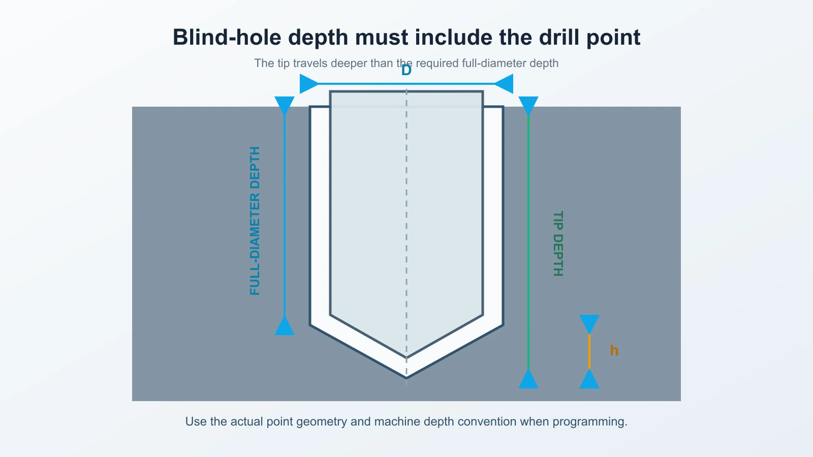
This is a geometry calculation, not a complete CNC cycle recommendation. Actual programmed depth must also account for the real point grind, machine conventions, breakthrough or bottom-clearance requirements, tolerance, and the tool documentation. The symmetric-point calculation above supplies the multiplier and worked example; the selected drill’s actual geometry remains controlling.
A Five-Step Selection Sequence
- Define the hole. Record material grade and hardness, diameter, full-diameter depth, tolerance, through or blind condition, entry surface, and exit condition.
- Filter by drill construction. Select a drill type and tool family intended for that material, depth, coolant delivery, and machine. Point angle is one field in this filter.
- Read the complete point description. Confirm included angle, split or thinned-web geometry, edge preparation, tool material, coating, and any pilot or spotting instructions.
- Check the process around the point. Verify runout, workholding, holder condition, spot geometry, feed continuity, coolant, and chip evacuation.
- Account for point height and validate. Add the point allowance for a blind hole, then prove the process under controlled conditions and inspect the hole.
The sequence is intentionally broader than a material chart. Point angle, chisel edge, cutting edges, flutes, and helix are related parts of the same cutting tool.
Choose the Drill as a System
Once the application is defined, compare the available constructions in the drilling tools. Use the collection to narrow the tool family, then confirm suitability for the material grade, hole diameter and depth, tolerance, machine, coolant delivery, and required point geometry. This link is a selection bridge, not a claim that one listed tool fits every row in the chart.
Diagnose the Result Instead of Blaming the Angle
When a process misbehaves, the symptom can point to a better next check:
| Symptom | Check before changing angle | Why |
|---|---|---|
| Drill wanders at entry | Runout, point symmetry, surface condition, spotting compatibility, tool length and rigidity | Location error can begin outside the angle choice |
| Outer corners chip | Spot angle, edge preparation, interrupted entry, runout and feed | Premature corner contact or impact can overload the lips |
| Thrust is high | Chisel/split geometry, web thickness, feed, tool wear and material response | The center geometry strongly affects thrust |
| Chips pack in the hole | Flute capacity, coolant, peck strategy, depth-to-diameter ratio and material | Point angle does not solve an evacuation limit |
| Blind hole is shallow at full diameter | Point-height allowance, actual grind and machine depth reference | Tip depth and full-diameter depth are not the same |
Real shop discussions often disagree about which angle “works” because the drill, machine, coolant, diameter, depth, and feed context differ. Treat that disagreement as a reminder to collect the missing variables, not as evidence that geometry is irrelevant.
The Practical Takeaway
Use the drill point angle chart to narrow candidates, not to declare a universal winner. A 118° point is a sensible general-purpose reference; a 135° point is a common flatter alternative. Then separate point angle from split-point geometry, check how the drill will be started and cooled, calculate the point allowance for blind holes, and follow the exact tool manufacturer’s application data.
That process takes slightly longer than choosing by material name alone. It also produces a decision you can explain, test, and repeat.