



Indexable Drill Failure: Checks Before You Restart
Before replacing the inserts in a burned or badly damaged indexable drill, record the condition of each insert position, inspect its pocket and screw, and check the chip and coolant paths. A new cutting edge is not a sufficient reason to restart if the seat, body or supply problem is still unresolved. Choose any speed or feed change after those checks, using the guidance for the actual drill, inserts and material.
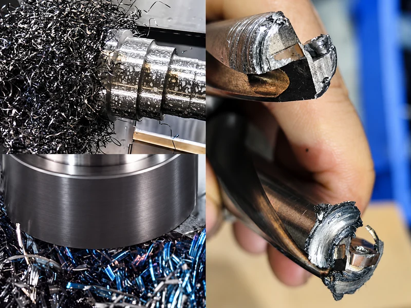
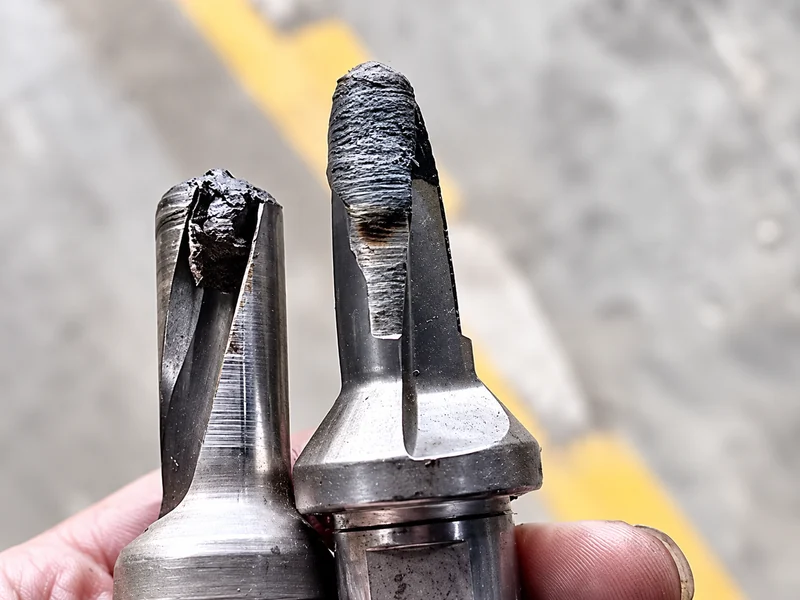
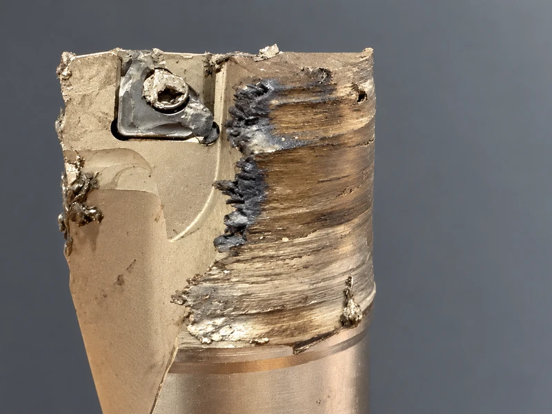
The final burned or “melted” appearance does not necessarily reveal the first failure. Heat damage may follow an earlier edge failure or evacuation problem; it does not, on its own, prove excessive speed or insufficient coolant. The task is to separate what survived the incident from what still needs to be established.
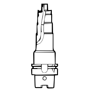
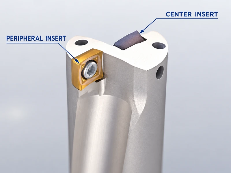
The checks below use the common U-drill arrangement with a center insert and a peripheral insert. Other indexable-drill designs need their own component map and instructions.
Preserve the evidence from each insert position
Stop safely, allow the tool and workpiece to cool, and isolate the machine as required by the site's procedures before inspection. Do not reach into a rotating setup to pull chips, probe a hole or clear a passage. Do not make another cut merely to reproduce smoke, glowing material or an abnormal load.
Before cleaning the drill or discarding damaged parts, photograph and label what can be inspected safely:
Center and peripheral inserts separately: identify the installed insert and edge, missing or chipped portions, wear, cracks and adhered material. If damage has destroyed a feature, record it as unobservable rather than guessing its earlier condition.
Each pocket, screw and the surrounding body: show the insert position before disassembly where possible, then record the supporting surfaces, fastener and thread condition during the approved inspection.
Flutes and retained chips: record where chips were wrapped, packed or stuck. Keep useful samples identified with the operation; do not assume that all chips in the final pile came from the same insert or stage of the cut.
Save the program and actual settings before changing them. Note the material, drill and insert designations, hole depth, tool overhang, coolant commands, and any recorded load or alarm change. State where in the cycle the first abnormal sign occurred and whether the failure followed indexing, remounting or a supply interruption.
Keep observation and explanation separate. “The peripheral edge is missing” is an observation. “It broke before the body was damaged” is a proposed sequence unless another record supports it. Record the later in-hole evidence as well as the apparently normal start.
Use specific wear terms only when the evidence supports them. Plastic deformation, thermal cracking, built-up edge and chipping are not interchangeable names for a burned tool. For help describing the surviving features, see how to identify the observed tool-wear pattern. Color, noise or smoke can prompt an inspection, but none is a stand-alone temperature measurement or root-cause test.
Check whether a new insert would have a sound working setup
Include the body, pocket and screw in the replacement decision
Inspect more than the replaceable edge. A burned or deformed pocket, damaged supporting surface, affected thread or damaged body requires assessment under the manufacturer's criteria or by a qualified service provider. Keep it out of service until that assessment establishes what can be reused or repaired. A new insert fitting into the pocket is not a serviceability test.
For a serviceable assembly, confirm the correct inserts, their specified positions, the approved screws, and the required seating and tightening procedure. Clean away obstructions using the prescribed method. Use the specified torque tool and tightening value; tightening harder by feel is not a substitute. Recent indexing does not rule out incorrect seating or an assembly error.
Check holding, support and overhang as part of the same setup. Identify whether the drill rotates or the workpiece rotates, then apply the installation checks for that arrangement. Do not transfer a stationary lathe adjustment into a rotating-drill setup simply because both operations use an indexable drill.
Follow both the chips and the coolant delivery
In the center/peripheral arrangement, both inserts generate chips that must leave through the drill's flutes. Check for retained material and obstruction rather than treating the outside of the burned body as the complete evidence. Wrapped chips, packed chips and material adhered to an edge are different observations, even when they appear together after failure.
Review the selected insert geometry and chipbreaker against the material and application. Chip formation changes with those conditions and the cutting data. Poor evacuation can contribute to breakage; use the retained chips and cycle record to investigate when a blockage developed.
Trace coolant delivery to this drill: check the relevant connections, filter and internal passages, as well as the program's coolant state during cutting. Verify delivery for this operation rather than inferring it from a running pump, another tool's results or flow outside the cut.
Use the machine and tool supplier's approved delivery checks. Do not use an exposed cutting test or reach into an operating machine to inspect flow. Confirm the selected drill's pressure and flow requirements and verify cleared passages by that approved method, not by a higher nominal pressure setting alone.
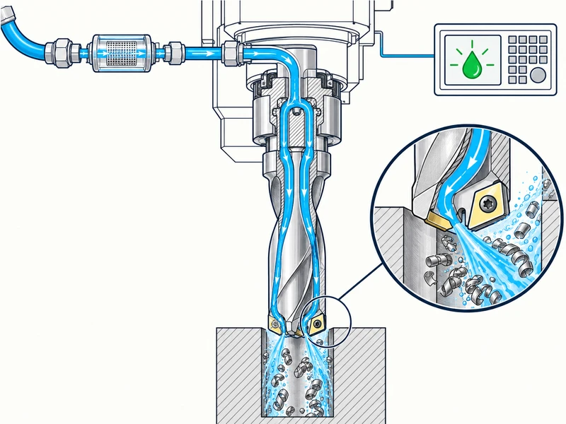
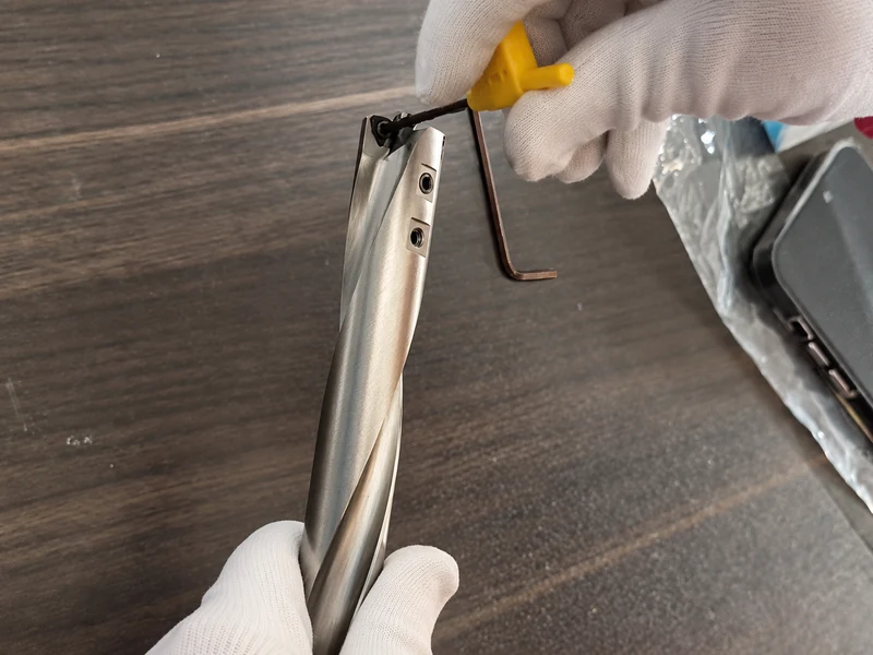
Normal indexable-drilling demonstration supplied with this article. It does not verify coolant delivery inside a failed setup or establish the cause of a damaged tool.
Use the evidence to choose a cutting-data question
Speed and feed can be part of the failure, but “burned” does not select an adjustment direction. The inner and outer cutting positions can show different damage, and a remedy for one condition may be unsuitable for another. For a crack pattern, review temperature cycling, supply changes and loading before deciding whether coolant quantity is involved.
For long chips, choose the adjustment from manufacturer guidance for the particular material and drill series: the direction can differ with chip formation and edge loading. Neither increasing feed nor reducing both speed and feed is a universal remedy. Start from the recommendation for the exact insert combination and material, not a twist-drill chart or a rule borrowed from another indexable-drill series.
Check what the control actually commanded: speed, feed mode and units, coolant state, and the motion at the point where trouble began. Entry, breakthrough, interrupted engagement or a changed hole condition may matter, but each needs to be checked against the tool's permitted application. Do not add or remove a pecking cycle as an automatic cure.
After the known setup and delivery defects have been corrected, frame the remaining parameter question explicitly: what observation should improve if this change is appropriate? Choose a change within the applicable manufacturer guidance and retain the other trial conditions where practical. That makes the next result interpretable rather than merely different.
Define the restart check before starting the next cut
Correct all confirmed unsafe defects before testing. “Change one variable” does not mean leaving a damaged seat or failed supply in place while trying a different feed. Record the repairs as a group; use controlled changes to investigate what remains uncertain only after the setup is serviceable.
Before a permitted trial, write down three answers:
What has been restored? Identify the assessed body and pockets, fitted inserts and screws, holding condition, cleared paths and verified coolant delivery.
What will this trial check? Record the material, cutting data and cycle, the proposed explanation, and the edge, chip or load observation that would support or contradict it.
What ends the trial? Define the stopping and inspection conditions with the responsible process personnel and the machine/tool instructions. Abnormal load, noise, chip retention or renewed damage calls for safe stopping and investigation, not continued cutting to finish the test.
After the trial, inspect both insert positions and the surrounding body again, and compare the chip, supply and load evidence with the record. If damage returns or its sequence remains unexplained, stop and escalate the tool, setup and records for technical review. Completing a hole with fresh inserts is only one result; the evidence must show that the unresolved failure condition is no longer being carried into the next cut. If the assessed assembly is serviceable but the hole is undersize, use the first-trial versus after-use undersize checks for that separate measurement problem.