



Indexable Drill Troubleshooting: When the Hole Is Undersize
If an indexable insert drill cuts undersize, first confirm the measurement and whether the hole changes along its depth. Then ask when the problem began. A small first trial hole puts insert assembly and installation near the top of the check list. A hole that becomes smaller after acceptable parts calls for a comparison with that earlier baseline. Neither pattern identifies a cause by itself.
Do not keep adding offset to chase a new size error. If the drill body is rubbing, an edge is damaged, or load or noise becomes abnormal, stop drilling and follow the machine's safe inspection procedure.
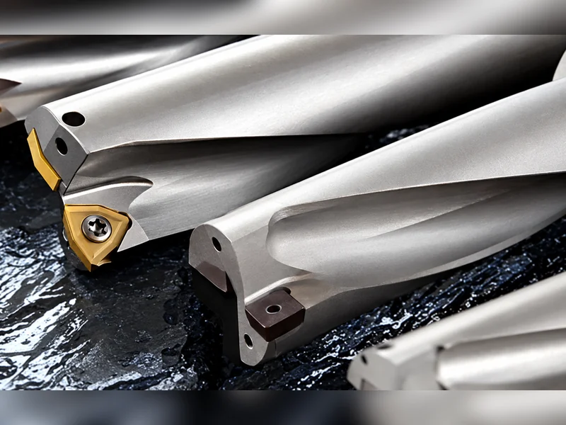
This guide concerns indexable insert drills, often called U drills—not letter-U twist drills or replaceable-tip drills. If the construction is unclear, see the differences between replaceable-tip and indexable insert drills.
Confirm what “undersize” means before changing the setup
Write down the drawing requirement, the drill's nominal diameter, and the measured result separately. A nominal drill size is not a guarantee that every drawing tolerance can be met directly by drilling. Check the selected drill's stated capability against the actual requirement.
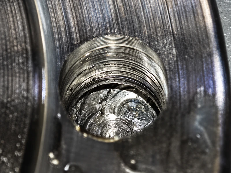
Use a suitable, verified measuring method and record where each reading was taken. Where access and the inspection plan permit, compare the entrance, an intermediate position, and the far end of the hole, in different angular directions. If you can only measure the entrance, record that limitation rather than describing the entire hole as uniformly small.
Keep part temperature, clamping condition, measurement location, and method comparable between trials. Otherwise, a changed reading can be mistaken for a changed cutting result. A hole that varies with depth or direction needs a hole-form investigation, not just a correction to one diameter reading.
| Observed pattern | Next check to prioritize | Evidence to retain |
|---|---|---|
| First trial hole is already small | Insert assembly, then installation for the actual rotating arrangement | Insert identities and positions; setup checks; measurements along the hole |
| Earlier parts were acceptable, then size decreased | What changed since the baseline: edges, seating, holding, coolant or chip control | Part sequence, first abnormal result, edge condition and load/chip changes |
| Size differs with depth or angular direction | Confirm hole form, then investigate alignment, stability and chip evacuation | A location-by-location measurement map, not one average diameter |
| No comparable earlier measurements exist | Establish a repeatable measurement baseline before diagnosing a trend | Method, locations, part condition and the first controlled trial result |
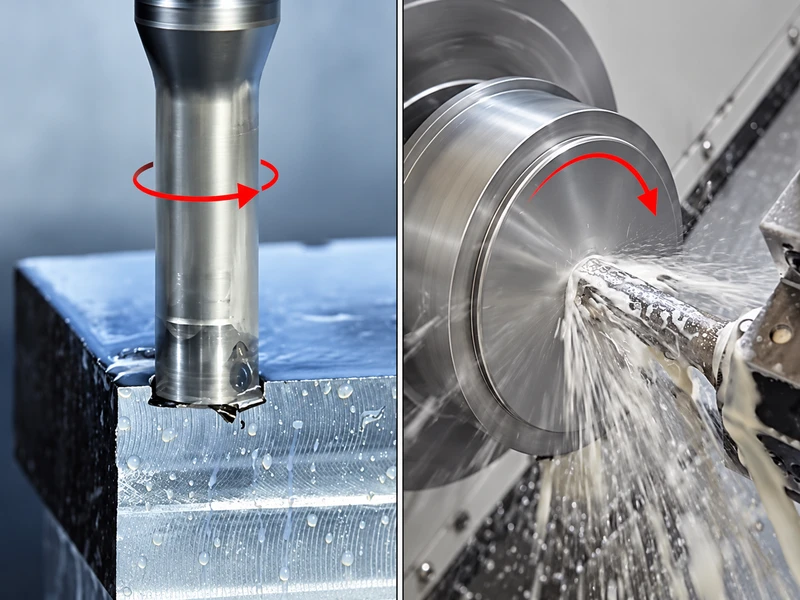
Before following either time-based branch, identify the cutting arrangement: does the workpiece rotate while the drill stays still, or does the drill rotate? The installation checks are not interchangeable.
If the first trial hole is already small
“New” does not mean correctly assembled or correctly installed. The same first-hole checks also apply after changing inserts, remounting the drill, or disturbing the holder.
Check the insert assembly
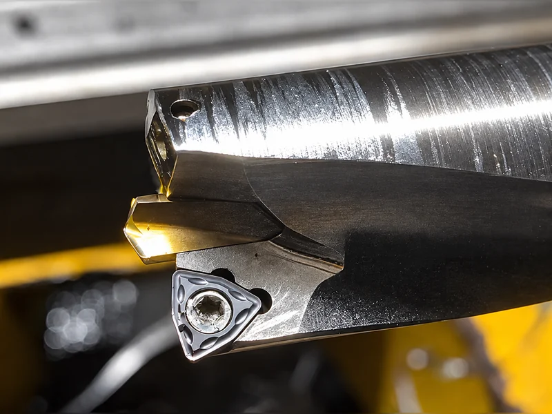
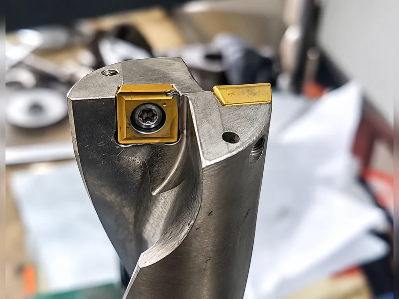
Confirm the drill body and insert designations against the manufacturer's instructions. Verify that the centre and peripheral inserts are in their specified positions and that their geometries are an approved combination. Do not assume that inserts which fit the pockets are interchangeable.
With the tool safely accessible, inspect and clean the seats. Check for obstructions, damage, and screw condition, then seat the inserts using the specified tightening procedure and torque tool. A new edge cannot compensate for a damaged or obstructed seat.
The peripheral cutting position deserves attention, but a casual caliper reading across two inserts is not a substitute for the manufacturer's dimensional reference. If an assembled dimension is in doubt, check it by the specified method before blaming the body or changing brands.
Workpiece rotating, drill stationary: check alignment first
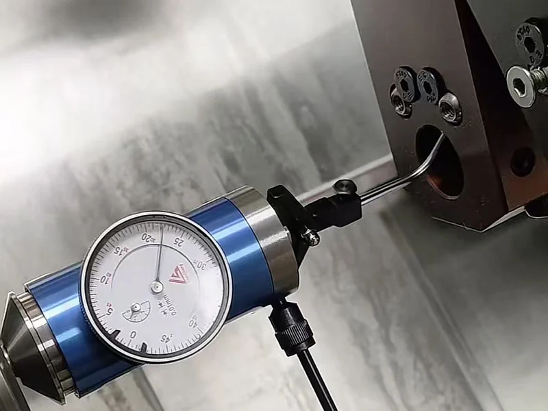
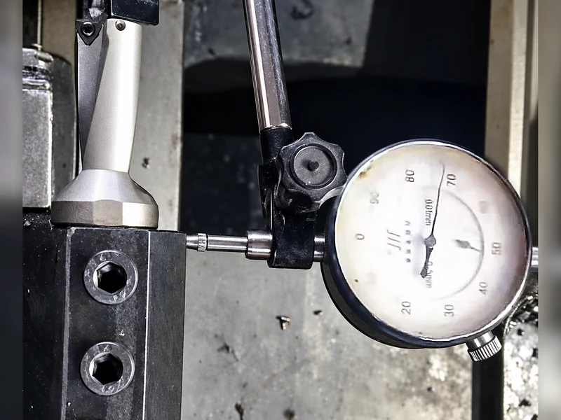
For a stationary drill on a lathe, prioritize centre-line alignment and whether the drill axis is parallel to the spindle axis. Checking one point does not establish parallelism. Follow the machine and drill supplier's procedure; a test bar and dial indicator can be used to investigate the alignment.
Also distinguish the static setup from its behaviour under cutting force. Turret deflection can affect the result even after a static alignment check. If hole size changes with cutting load, investigate mounting and stability with the process engineer rather than treating the offset value as the diagnosis.
Do not rotate the shank to a different orientation as a universal test. Any orientation trial must suit the shank flats, clamping arrangement, and supplier's procedure.
Drill rotating: check the installed rotating assembly
Check the holder, clamping, seating and runout at the reference specified for that tool system. Runout is a setup condition to verify—not proof that it caused the undersize hole.
For this arrangement, also check coolant delivery: flow, the filter, and the drill's internal coolant passages. Confirm the centre/peripheral insert geometry combination for the material and application. These checks belong in an undersize investigation even when the holder appears satisfactory.
Use the recommended cutting-data range for the exact drill and inserts. Changing speed and feed repeatedly before correcting an assembly or delivery problem makes the trial harder to interpret.
If the hole becomes smaller after acceptable parts
Start with the last acceptable result. Did the decrease develop gradually, or did it appear immediately after an insert change, remount, coolant interruption, or another recorded change? Compare the same measurement positions and conditions before deciding that the tool is progressively cutting smaller.
Inspect the peripheral edge for wear, chipping and adhered workpiece material. Inspect the centre edge as well; do not isolate one insert from the rest of the cutting system. Check seats and holding for changes, and compare coolant delivery, chips and machine load with the acceptable run.
Wear can take a hole out of tolerance, but the timing alone does not prove a particular wear mechanism. Likewise, material stuck to an edge is an observation to investigate, not a reliable prediction of which direction the diameter must move.
If the body, seats and installation are serviceable and a new edge is appropriate, index or replace the insert according to its instructions. Keep the other trial conditions unchanged where practical, then measure again. Recovery toward the baseline supports an edge-related explanation; it does not explain why that edge deteriorated or rule out a condition that will damage the next one.
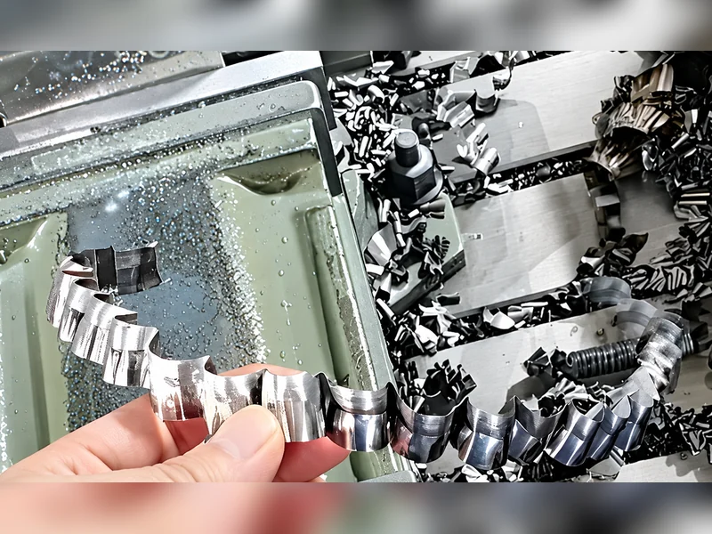
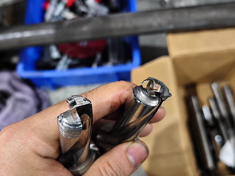
If the result does not recover, return to installation, stability, coolant and chip evacuation. If the hole is tapered or the body has rub marks, investigate those findings directly. Replacing inserts repeatedly or compensating each smaller reading can conceal a problem still present in the setup.
When radial adjustment is—and is not—the next step
Radial pre-setting can be legitimate for a stationary indexable drill when the specific tool permits it. It belongs after the measurement, edges, seating and installation have been checked—not in place of those checks.
The permitted range depends on the drill design, including overlap between the centre and peripheral inserts. Confirm the approved direction, range, insert orientation, and the control's radius/diameter convention before making a controlled trial. There is no universal X-offset sign or amount for an undersize U-drill hole.
Do not set the drill to cut below its nominal diameter unless the tool supplier explicitly approves that application; the body can interfere with the hole wall. Holder travel is not, by itself, the drill's allowable adjustment range.
A rotating drill may also permit diameter pre-setting through a compatible adjustable holder or eccentric sleeve. That is a different setup—not the stationary-drill coordinate-offset method. Simply moving a rotating drill's programmed hole location does not change its cutting diameter.
If the drawing requires tighter size or form control than the qualified drilling process can deliver, plan a suitable finishing operation. Do not assume that more compensation will turn an unstable drilled hole into a finished, conforming bore.
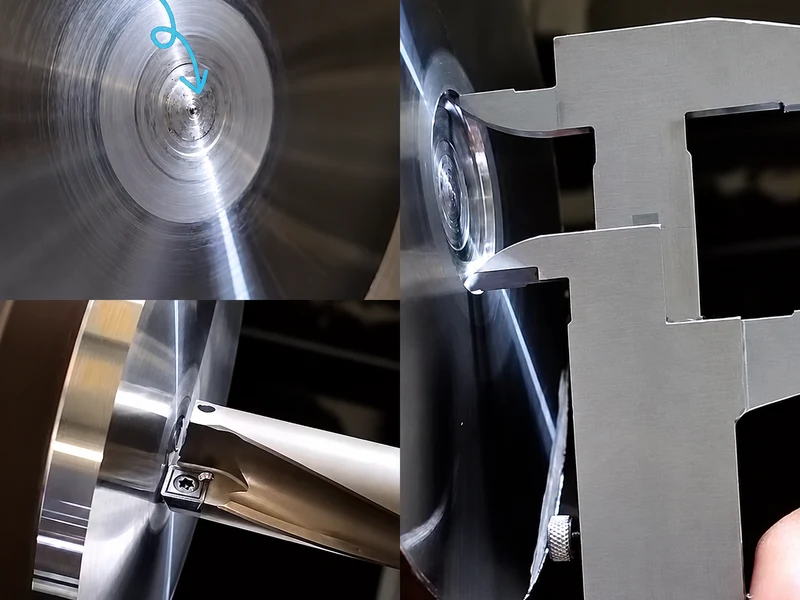
Make the next trial produce useful evidence
Before the next safe trial, keep a short record that another operator or application engineer can reproduce:
Configuration: drill series, nominal diameter, working length, holder, rotating arrangement, and centre/peripheral insert designations.
Starting point: first trial, after a change, or after a known sequence of acceptable parts.
Measurement map: location, direction, method, drawing limit, and part condition for each reading.
Observed changes: edge condition, body rub marks, chips, coolant delivery, load and unusual noise.
One controlled change and its result: what was changed, what remained constant, and the corresponding measurements.
Use that record to choose the next check. Once size and hole form return to the required condition, continue checking with the same method to confirm the result holds through the production run. A recovered trial hole is a useful result; it is not yet evidence that the original problem cannot recur.