



CNC Tool Holder Types: How to Choose for Drilling, Milling and Reaming
Choose a CNC tool holder around the operation: secure grip for demanding rough milling, accurate alignment for reaming, or flexible setup for frequent changes between shank diameters. The right choice can differ between jobs on the same machine.
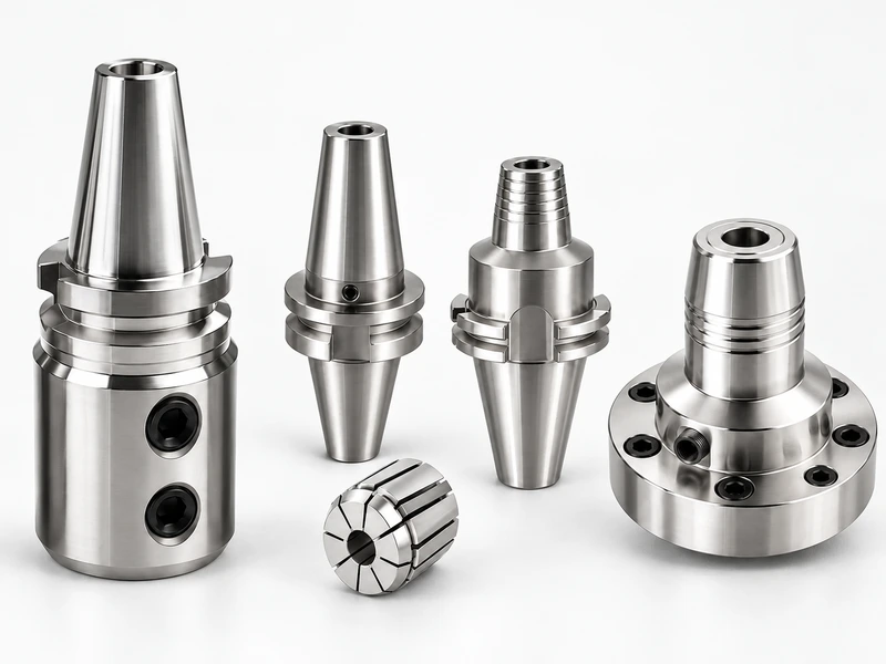
This guide compares five useful approaches for these drilling, milling and finishing jobs: side-lock, ER collet, hydraulic, shrink-fit and an adjustable flange-style system. It is a practical shortlist, not a complete catalogue of CNC toolholding systems. The choice comes down to what the operation demands most: torque transmission, runout control, stiffness, access or changeover convenience.
First confirm the machine connection. BT, SK and HSK identify spindle interfaces; ER, hydraulic and shrink-fit describe how the cutter is gripped. A BT holder can therefore have an ER or a hydraulic front end. Match the exact spindle interface, size and retention arrangement before comparing the five holding approaches below.
| Machine spindleMachine-side connection | Tool holderInterface at the back Clamping system at the front | Cutting toolDrill, end mill, reamer or compatible boring tool |
Which tool holder should you consider first?
| Holder type | A useful starting choice when… | The main tradeoff |
|---|---|---|
| Side-lock | Rough milling puts a compatible flat-shank cutter under substantial load. | Secure mechanical engagement takes priority over the lowest runout. |
| ER collet | You need economical, versatile clamping for different shank diameters and routine operations. | Accuracy depends on the collet grade and the complete assembly; the nut also needs clearance. |
| Hydraulic | You need accurate, convenient changes for drilling, reaming or a suitable milling operation. | Choose a model with the required load capacity; easy setup does not make every design a roughing holder. |
| Shrink-fit | Milling or finishing calls for a rigid, concentric assembly, sometimes with a slim nose. | Heating and cooling equipment, compatible shanks and controlled handling become part of the process. |
| Adjustable flange-style | A precision finishing job needs correction of the mounted assembly's runout. | Fine adjustment and verification take time; the particular design determines its cutting-load capability. |
1. Side-lock: choose grip for demanding roughing cuts
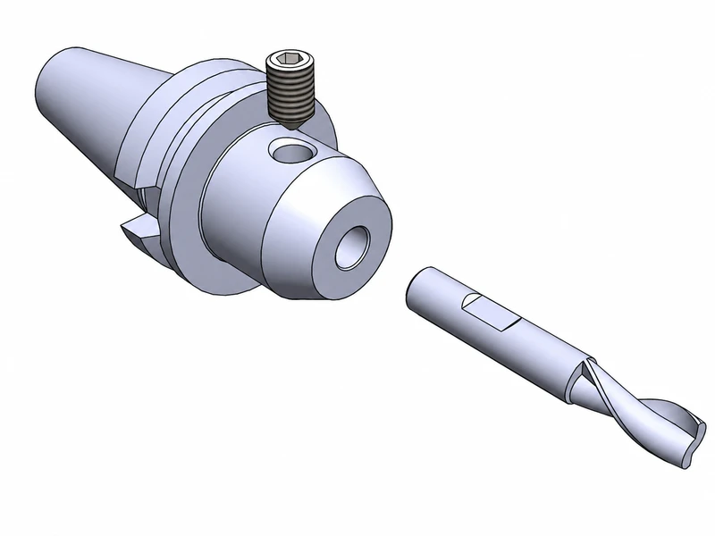
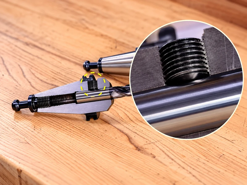
A side-lock holder uses a screw against the specified flat on the cutter shank. That engagement makes it a practical choice for rough milling where transmitting torque and retaining the cutter matter more than achieving the smallest possible runout.
Consider it when the cut removes substantial stock and the cutter has the correct shank form. Choose it for the cutting load; material hardness alone does not establish the need. A heavy cut in a relatively easy material can still place significant demands on the grip.
The compromise is alignment. A conventional side-lock arrangement is usually less attractive for a finishing operation whose result is sensitive to small changes in runout. If the same cutter must produce a demanding finished wall or floor, check whether its mounted accuracy meets that requirement before accepting the holder because it grips securely.
Use the specified shank flat, screw position and tightening procedure. A smooth shank in a holder intended for a flat is not an equivalent assembly. For higher spindle speeds, check the holder's speed and balancing requirements as well as its grip.
2. ER collet: choose versatility and an economical setup
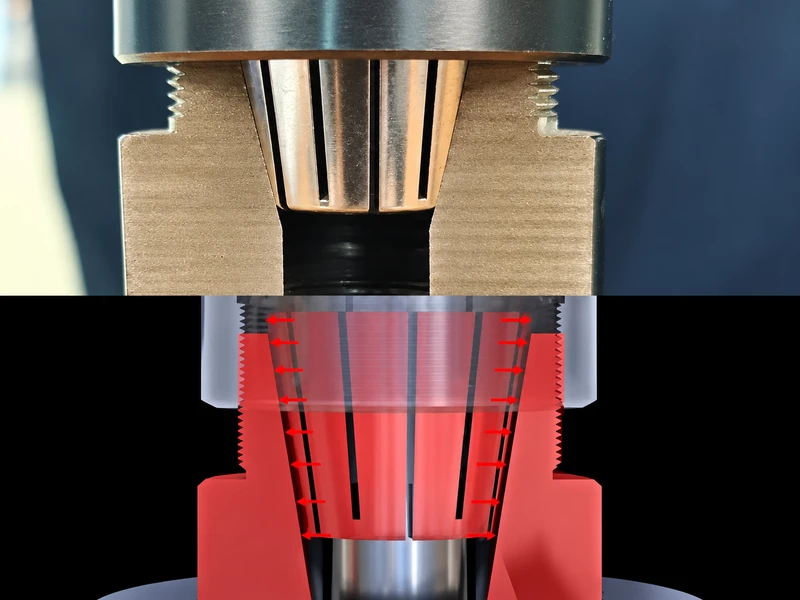
An ER holder closes a slotted collet around the shank as the nut is tightened. Changing the collet lets the same holder accommodate different shank diameters within its system. That makes ER a useful starting point for routine drilling and general-purpose machining, especially when a shop frequently changes tools.
For tapping, the assembly also needs to suit the machine's tapping method and the tap's torque requirements. Do not assume that an ordinary round-shank collet provides every feature of a dedicated tapping holder.
ER accuracy is not one fixed number. The collet, holder bore, nut, tool shank and assembly condition all matter. A precision-grade collet can be worthwhile, but its component specification does not guarantee the same reading at the cutting edge after mounting.
For everyday work, choose ER when its measured assembled runout and grip satisfy the job. For precision finishing, compare a suitable high-accuracy ER assembly with the alternatives rather than either dismissing all ER holders or accepting any collet marked “precision.” Check the permitted clamping range, minimum engagement and tightening torque. Where access is tight, include the nut diameter in the clearance check.
3. Hydraulic: choose accuracy with convenient tool changes
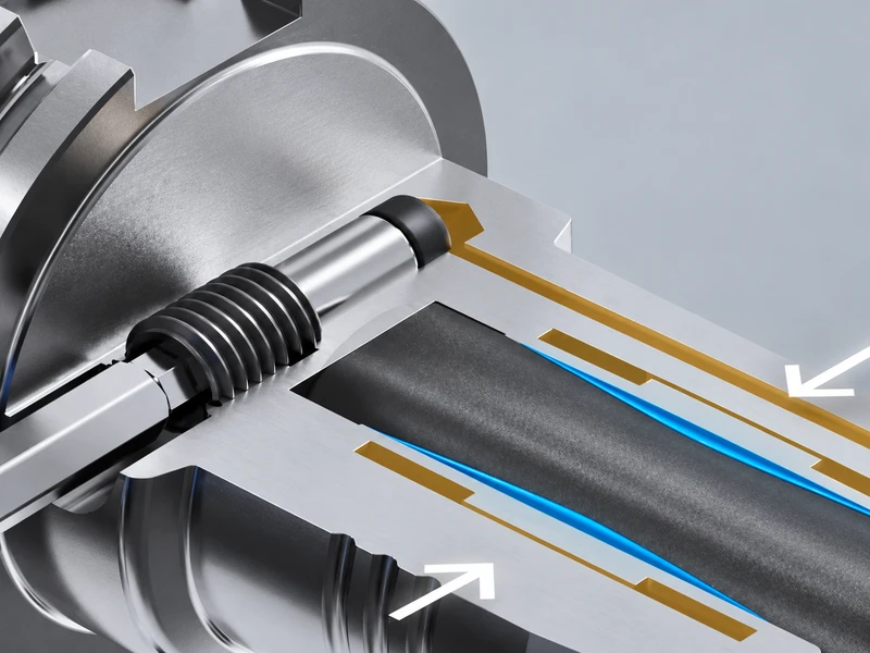
A hydraulic expansion holder uses pressure to deform a clamping sleeve around the shank. On common designs, operating an actuation screw clamps or releases the tool. There is no shrink-fit heating cycle, and a standard nonadjustable design does not require an operator to dial in the runout for every change.
This combination is useful for drilling, reaming and finishing work where consistent assembly and straightforward handling both matter. If tool changes are frequent, setup convenience can be a real production advantage rather than a minor purchasing detail.
Milling-rated hydraulic holders also cover demanding cutting applications. Equally, a holder selected for convenient reaming cannot automatically be reassigned to a demanding roughing cut. Check the specific model's approved operation, clamping diameter, engagement and transferable torque.
Where reduction sleeves are permitted, use the specified components and account for the resulting assembly. Choose hydraulic over shrink-fit when it meets the cutting requirements and avoids equipment or handling that the shop does not otherwise need.
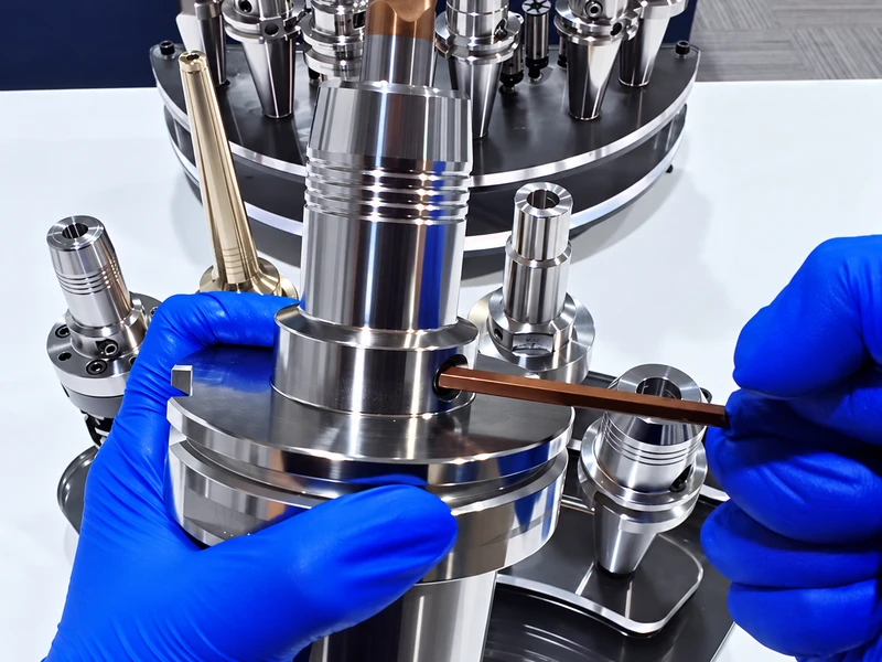
4. Shrink-fit: choose a rigid grip for milling and finishing
A shrink-fit holder is heated so its bore expands enough to accept the cutter. Controlled cooling then creates an interference grip around the shank. The compact clamping structure makes shrink-fit useful where concentricity and stiffness both matter.
It is a strong candidate when an end mill needs both a secure grip and low runout, or when a slim holder nose helps reach a feature without extending the cutter unnecessarily. Keeping the assembly short where clearance permits is often as important as choosing the clamping family.
The cost includes more than the holder. The shop needs suitable heating and cooling equipment, compatible shank dimensions and materials, and a repeatable changing procedure. For occasional tool changes, that investment may not be justified. Where a shrink-fit station is already part of production, the calculation is different.
For heavy cuts, verify the design's grip and pullout resistance as well as its runout. Follow the approved heating cycle and inspect the bore and shank: overheating or damage can reduce the grip. Base replacement on the specified service criteria and holder condition rather than a fixed cycle count for all shrink-fit holders.
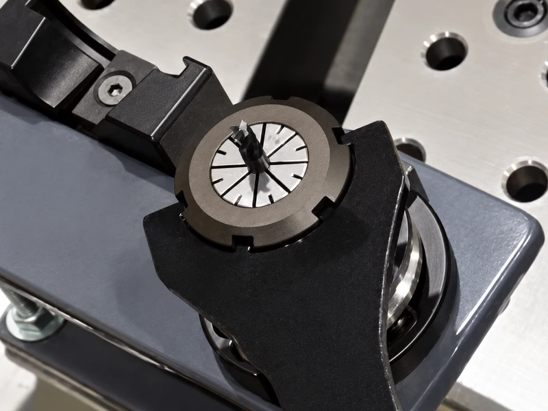
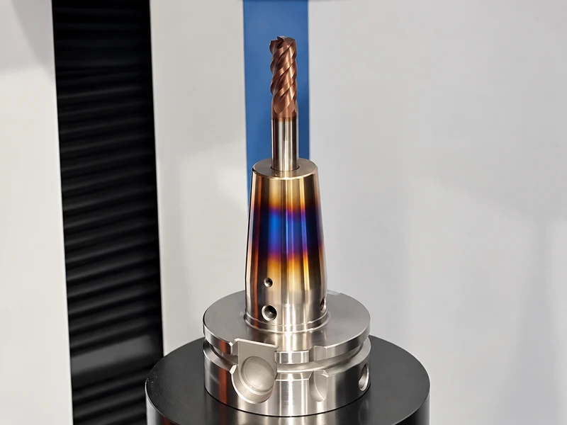
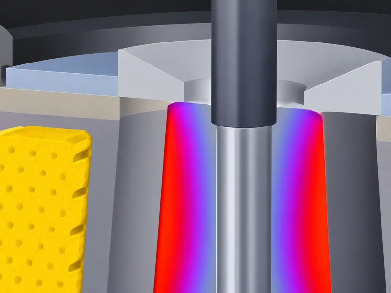
5. Adjustable flange-style: choose correction of mounted runout
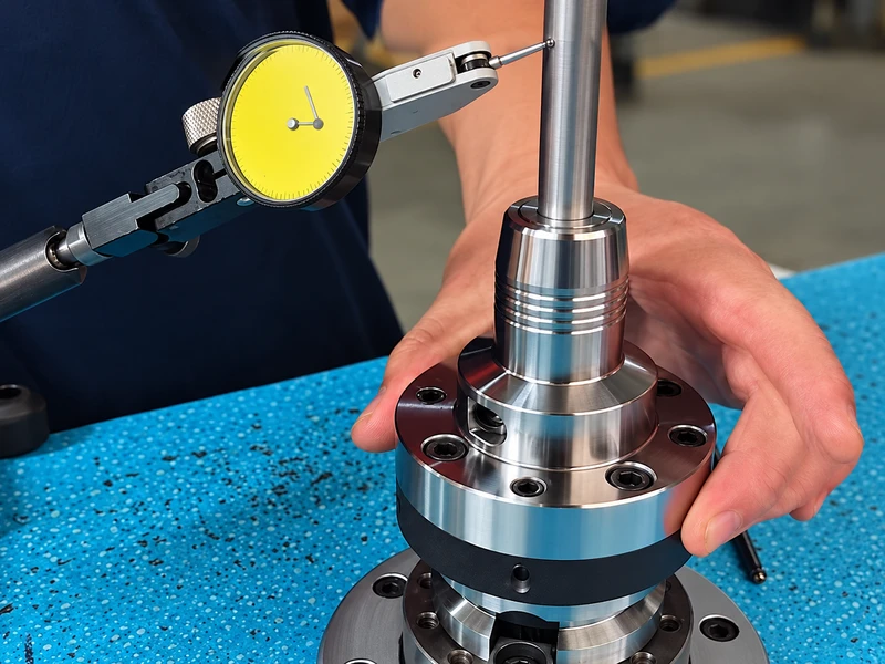
An adjustable flange-style assembly adds a way to align the mounted tool using adjustment screws. Its value is the ability to measure the assembled condition and correct it, rather than relying solely on the nominal accuracy of the separate parts.
Consider this approach for precision finishing when the remaining alignment error affects the result, as in a demanding reaming setup. It can be useful when a sound, correctly assembled fixed holder still cannot meet the required runout at the working position.
The tradeoff is setup effort. Adjustment, locking and rechecking need time and suitable measuring equipment. A very small indicator reading also does not establish literal zero error throughout the assembly or under cutting load.
“Adjustable flange” is a description of an arrangement, not one universal clamping standard. Confirm what the particular design adjusts, which tool connection it accepts and what load it supports. Specify the actual system and its adjustment procedure rather than ordering on the description “high precision” alone.
How accurate are these holders in practice?
Compare the measurement conditions before comparing the numbers. A runout specification should identify the product, whether it concerns a component or an assembly, and where the reading is taken. A value measured near the nose cannot simply be substituted for a requirement farther along the cutter.
TIR means total indicator reading: the difference between the maximum and minimum readings over a complete rotation at the stated measuring position. Published values need that position and the identity of what was measured.
| Published example | Stated runout | Measurement condition |
|---|---|---|
| REGO-FIX standard ER collet | TIR ≤10 μm | 3 × D; a collet-grade specification |
| REGO-FIX ER-UP collet | TIR ≤5 μm | 3 × D; a collet-grade specification |
| SCHUNK TENDO Silver SK40, Ø25 × 80.5 | <3 μm | 2.5 × D; this specific hydraulic holder |
Here, the multiplier expresses a measurement distance relative to the specified diameter D. Use each manufacturer's inspection definition for the diameter, gauge and starting datum. These examples describe different products and conditions—not a universal ranking or a guarantee for your spindle–holder–tool assembly.
The useful number is the verified reading for the chosen assembly at the position relevant to the cut. Record the measurement location and tool projection. For fine finishing, use an appropriate inspection method near the working end; do not treat a shank reading as proof of every cutting edge's position. Nor does low runout alone guarantee stiffness, balance or the required finished-hole tolerance.
Apply the choice to the operation
Drilling: start with the hole and drill requirements
ER, hydraulic and compatible side-lock holders are practical candidates. ER offers flexibility; hydraulic offers convenient accurate changes; side-lock can suit a compatible drill shank where secure drive is important. Check coolant delivery and the specified runout limit alongside grip.
Do not accept a drill assembly merely because no wobble is visible. Small-diameter drills and demanding holes can be sensitive to errors that are not obvious by eye. The drill manufacturer's limit and the part requirements should govern acceptance.
Milling: distinguish stock removal from finishing
For heavy stock removal, first establish that the holder can transmit the load and resist cutter movement. Side-lock and suitable shrink-fit holders are useful starting candidates; milling-rated hydraulic and other systems may also qualify.
For a finishing pass, give more weight to mounted runout, projection and stiffness. A grip that survives roughing may still be a poor choice for the required surface. Conversely, the lowest catalogue runout does not compensate for an unnecessarily long or insufficiently rigid setup.
Reaming: give assembled alignment more weight
Hydraulic and shrink-fit holders are useful candidates for accurate, repeatable reamer mounting. Consider an adjustable system when the job requires deliberate correction of residual assembled runout. The extra adjustment should solve a measured problem, rather than simply add complexity.
Check the incoming hole, reaming allowance and alignment as well. Changing the holder cannot by itself correct every cause of oversize, poor roundness or an unsatisfactory finish.
Boring: identify the tool connection first
A suitable straight-shank boring tool may use hydraulic or shrink-fit clamping, while a precision modular boring assembly may have its own flange or other dedicated connection. Choose within that actual system. Adjusting a boring head's cutting diameter and correcting the assembly's alignment are separate tasks.
If a good tool runs badly on the machine, check the assembly
A cutter can pass inspection on its own and still show excessive runout when mounted. The on-machine reading includes the spindle connection, holder, clamping components and tool. Replacing the cutter repeatedly may leave the actual error untouched.
With the machine stopped and made safe for inspection, check the mating surfaces and shank for contamination or damage, then assemble by the specified procedure. Measure again at the same location and projection. If the error remains, use a suitable reference or known-good component to isolate one connection at a time. Inspect the cutter separately using appropriate datums; between-centres measurement is only suitable where the tool and inspection method support it.
Choose for the demand that controls the job
Finish the choice by checking the exact holder against the cutter shank, projection, cutting load and required accuracy. Then verify the assembly. Choose the assembly that repeatedly meets the part requirement at a setup cost the shop can sustain.
Share the workpiece drawing and existing holder interface for an application review.