Skip to content
Positive vs Negative Rake End Mills: Cutting Action and Selection
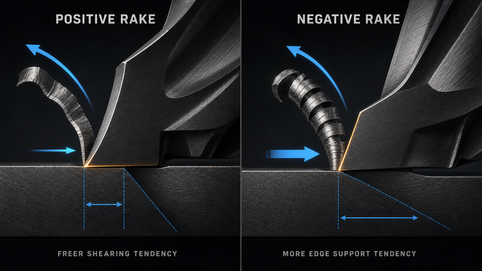
A positive vs negative rake end mill comparison is really a comparison of cutting action and edge support. A more positive effective rake tends to shear material with lower cutting force and easier chip flow, but leaves a thinner wedge behind the edge. A more negative effective rake tends to support a stronger wedge, but usually demands more rigidity, power and workpiece support.
That is a direction of tradeoff, not a universal ranking. Before choosing, identify which rake angle is being discussed, how it is produced on the assembled cutter, and whether the evidence comes from a solid end mill, an indexable milling body or a turning tool. The same label can hide different radial and axial geometry.
As an initial decision, choose a more positive direction when force or chip flow is the limiting constraint and verified edge strength remains sufficient; choose more edge support when interruption or edge damage is limiting and the machine-fixture system can carry the added force. Then confirm the exact toolmaker geometry instead of selecting from that rule alone.
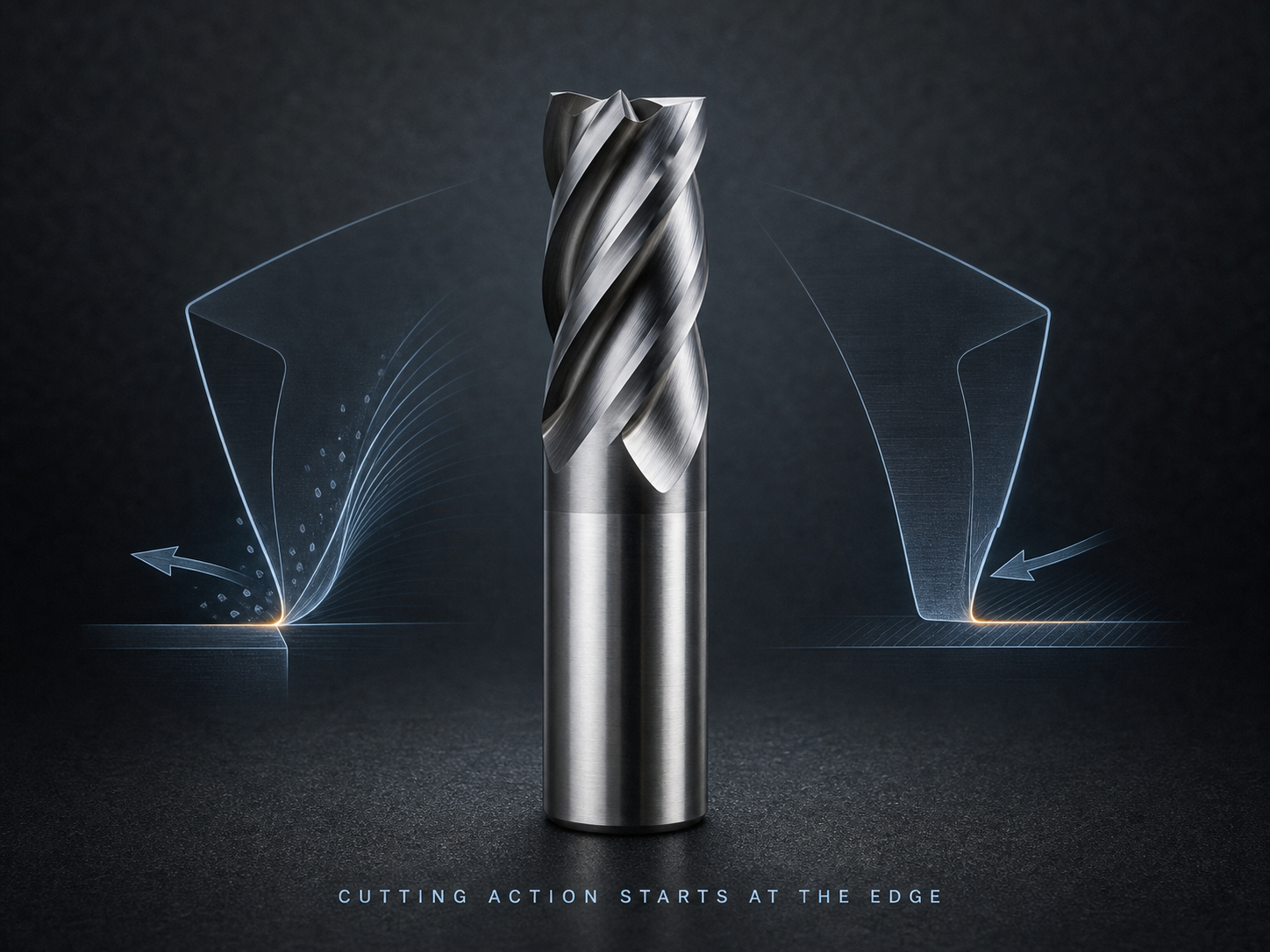
Locate rake on the actual cutter
The rake face is the surface over which the chip flows immediately after the cutting edge separates it from the workpiece. Rake angle describes the orientation of that face relative to a defined reference. Positive, neutral and negative therefore have meaning only when the reference plane and cutting direction are known.
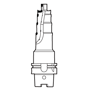
On an end mill, geometry is three-dimensional. Radial rake describes the cutting-face orientation in a section normal to the tool axis and is closely tied to the peripheral edge’s cutting action. Axial rake is evaluated in an axial reference section through the cutter axis and the local cutting point; it describes the face inclination in the axial direction and influences axial cutting action and chip movement. The manufacturer’s drawing controls the exact reference plane and positive/negative sign convention. A helical flute means these relationships evolve along the edge rather than appearing as one flat two-dimensional tool sketch.
Several nearby terms are not substitutes for rake:
- Helix angle describes the flute’s spiral relative to the tool axis. It influences entry timing, force direction and chip transport, but helix angle is not automatically the radial rake or axial rake.
- Clearance angle is behind the cutting edge and prevents the flank from rubbing the newly machined surface. It is not the chip-flow face.
- Wedge angle describes material contained in the cutting wedge. Changing rake while holding other geometry fixed changes wedge support, but real tools may change several features together.
- Edge preparation—sharp, honed, chamfered or otherwise prepared—modifies the local cutting action. A prepared edge can behave differently from the broad nominal rake behind it.
- Core thickness and flute depth affect tool stiffness and chip space. They can constrain the rake a designer can use, but they are distinct dimensions.
When a catalog says “positive geometry,” ask whether it means nominal radial rake, axial rake, effective cutting action, an insert style or a family-level description. For a defensible comparison, obtain the exact tool drawing or manufacturer definition.
Do not judge effective rake from appearance alone
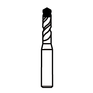
A solid carbide end mill is ground as one body. The visible flute face, edge preparation, core and helix combine to produce its local geometry. Looking at a photograph from an unknown angle is unreliable: perspective can make clearance look like rake, and a helical edge does not present the same section everywhere.
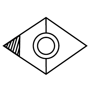
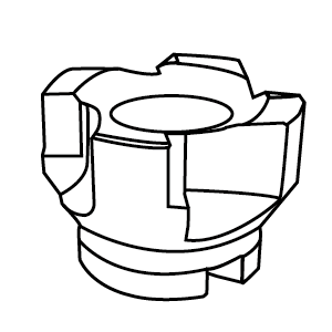
An indexable cutter adds another layer. The insert may have a flat-looking top, molded chipbreaker or nominal positive/negative style, while the cutter pocket tilts it radially and axially. Effective rake at the engaged edge comes from the insert geometry plus pocket orientation. A nominally negative insert can still produce a freer-cutting local geometry through its top form; a positive insert can be mounted in a body that changes one component of the assembled rake.
This distinction explains why experience from turning holders or indexable face mills cannot be copied directly into solid-end-mill selection. Those sources can support the mechanism—force, wedge support, rigidity demand—but not prove that a solid cutter with the same verbal label has identical geometry or performance.
The only reliable identification is tool-specific. Use the manufacturer’s radial and axial rake definitions, insert/body combination where applicable, edge preparation and application data. If those are absent, describe the cutter by verified family and observed cutting behavior rather than inventing an angle from appearance.
A useful drawing review asks four separate questions. Where is the engaged cutting edge? Which surface receives the chip at that point? In which plane is the angle stated? Does the published value describe nominal grind or effective assembled cutting geometry? For indexable tools, also verify that the insert designation, seat and cutter body match the drawing. For solid tools, confirm whether the published geometry applies to the peripheral edge, end cutting edge or both. This prevents a catalog comparison from pairing unlike quantities.
Inspection after regrinding or damage needs the same discipline. A changed flute face, reduced diameter or altered edge preparation can change cutting behavior even if the tool still resembles its original form. Do not infer the remaining rake from a photograph; compare against the approved regrind specification or replace the tool for a controlled test.
More positive rake favors freer shearing
Moving the cutting face in a more positive direction generally creates a sharper cutting wedge. Material can shear and move across the rake face with less resistance, so cutting force and power demand tend to decrease. This can help when the machine, holder, workpiece or thin feature cannot tolerate high force.
Easier chip flow can also be valuable in materials that form long or adhesive chips, provided flute space, surface condition, coating and coolant strategy suit the application. A freer-cutting edge may reduce the tendency to push a flexible workpiece away and may improve finish where force-induced deflection is the limiting problem.
The cost is support behind the edge. With less wedge material, the cutting edge can be more vulnerable to chipping under interruption, scale, impact, excessive chip load, unstable engagement or abrasive material. “Positive” does not mean fragile in every tool—carbide grade, edge preparation, core design and engagement matter—but the support tradeoff remains part of the selection.
More positive is also not synonymous with sharp enough for every nonferrous application. Polished flute condition, edge hone, coating affinity, chip space and effective diameter can dominate. Conversely, a well-supported positive geometry may work in steel when supplied for that condition. Material names alone do not settle the choice.
More negative rake favors edge support
Moving the rake face in a more negative direction generally retains more material in the cutting wedge. That edge-support tendency can be useful when the cut imposes impact, interruption, compressive loading or conditions that would chip a more acute edge.
The stronger wedge does not create free durability. It commonly raises cutting force and power demand and can push harder on the tool, spindle, holder, workpiece and fixture. If the system is light, has long tool reach, weak support or excessive runout, a nominally strong edge can still fail because the assembly deflects or chatters. Practitioner reports of negative-rake indexable cutters behaving poorly on lighter machines illustrate this condition dependency; they do not establish a universal machine-size threshold.
Chip formation and heat distribution also change with geometry. A more negative cutting action may compress the material more strongly and require a condition that supports stable chip formation and evacuation. Tool grade, edge preparation and coolant or air delivery remain coupled variables. Negative rake is not a license to increase load without checking the selected manufacturer data.
For a solid end mill, the phrase “negative-rake end mill” may be less informative than the exact radial rake, axial rake and edge design. Some cutters combine different directions in different planes to balance force direction, edge support and chip movement. Selection should follow the defined geometry rather than a binary marketing label.
Compare the tradeoffs on the same dimensions
| Decision dimension | More positive rake tendency | More negative rake tendency |
|---|---|---|
| Cutting action | Freer shearing with a more acute wedge | More compressive action with a more supported wedge |
| Cutting force and power | Lower-force tendency under matched conditions | Higher force and power demand under matched conditions |
| Edge support | Less material behind the edge; more sensitive to impact if other features do not compensate | More material behind the edge; can better resist some interrupted or heavy loading |
| Chip flow | Often easier flow across the rake face | Can demand more deliberate chip-forming and evacuation conditions |
| System rigidity | More tolerant when force capacity or workpiece support is limited | More dependent on spindle, holder, fixture and workpiece rigidity |
| Common selection risk | Choosing sharpness without enough edge support | Choosing edge support that the machine or setup cannot drive stably |
These are matched tendencies, not guarantees. They assume the same material, diameter, edge preparation, coating, engagement, reach and machine. A real product comparison rarely holds every variable fixed, so the table is a reasoning aid rather than a product ranking.
Let the weakest part of the system decide
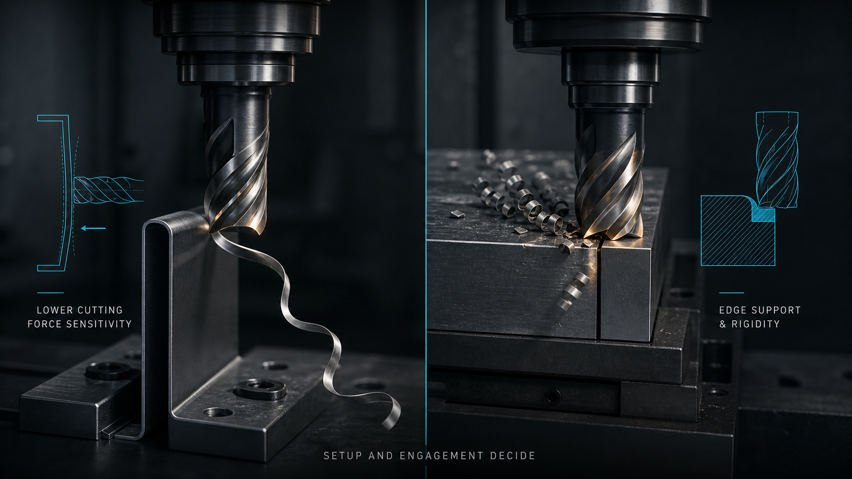
Rake selection cannot be separated from the force path. A long, small-diameter end mill on a flexible wall may need lower cutting force even if the material could tolerate a stronger wedge. An interrupted cut on a rigid machine may prioritize edge support. An indexable cutter with robust inserts may still perform poorly if the spindle, holder or workholding allows movement.
Evaluate machine power and torque in the actual speed range, spindle and holder condition, tool diameter and reach, runout, radial and axial engagement, fixture stiffness, unsupported workpiece span and cutting-force direction. The weakest element determines how much force and impact the process can carry.
Runout deserves special attention. If one flute carries most of the chip, the intended average chip load and edge-support calculation no longer describe the actual cut. Correct seating and holder problems before judging rake geometry. Chatter likewise confounds the comparison: an edge can chip because instability creates impact, not because its nominal rake is inherently wrong.
When a geometry change reduces force but size remains unstable, the workpiece or tool may still be deflecting. When a stronger edge survives but load and chatter rise, the system may not be rigid enough for that cutting action. Read the whole response rather than declaring one rake “better.”
Choose from the complete application tuple
Start with the operation and material condition: workpiece alloy, hardness, heat treatment, scale, interruption, abrasive inclusions, radial and axial engagement, entry and exit, slotting versus side cutting, roughing versus finishing, reach, coolant or air, chip space, dimensional target and surface requirement.
Then compare actual cutter families. The carbide end mill is a navigation point for candidate dimensions and families, not proof of a rake angle or application fit. Confirm the exact item’s drawing, geometry description and cutting-data conditions before programming it.
Use rake as one selection dimension among edge preparation, flute count, helix, core, coating or surface treatment, carbide grade and chip space. For an indexable cutter, verify both insert and body; replacing only the insert style may change effective rake, edge height, clearance or cutting diameter.
A practical decision boundary is:
- favor a freer-cutting direction when force, power, thin-wall deflection or chip flow is the limiting factor, provided the edge remains adequately supported;
- favor more edge support when interruption or edge damage is the limiting factor, provided the machine and setup can carry the resulting force;
- reject the binary choice when the manufacturer does not define the geometry or when a setup defect prevents a fair comparison.
Read failure evidence without blaming rake alone
High load can support the hypothesis that cutting action is too demanding, but first check chip load, engagement, dull edges, built-up material, runout and evacuation. Chatter can increase with a higher-force geometry, yet tool reach, holder condition, spindle speed and workholding may be the root cause.
Chipped edges can indicate insufficient support, but they can also result from recutting chips, impact at entry, excessive runout, thermal cycling or unstable motion. Rubbing and poor finish can suggest an edge that is not shearing freely, but feed per tooth, edge hone, coating affinity and effective cutting diameter also matter.
Use a controlled comparison. Hold tool diameter, reach, holder, material, engagement and cutting data within the respective manufacturer guidance. Change the intended geometry variable with a known tool, predict the response, and inspect load, chips, sound, surface, size and every edge. If several variables change, treat the result as a new process rather than proof about rake alone.
Verify the selected geometry in the real cut
Qualification should record exact tool identity, radial rake and axial rake definitions if published, helix and edge preparation, solid or indexable construction, insert/body combination, material condition, holder/runout, reach, RPM, feed per tooth, engagement, coolant and toolpath.
Inspect chip formation and evacuation, spindle load trend, sound, dimensional deflection, surface finish, burrs, built-up material, edge wear and repeatability. The expected outcome should match the selection reason: a freer-cutting geometry should reduce the force-related symptom without unacceptable edge damage; a more supported edge should improve survival without creating unstable force or poor chip control.
Release the cutter only for the proven condition window. If material hardness, interruption, reach, fixture, engagement or tool family changes, recheck the rake decision. Positive and negative rake describe useful cutting tendencies, but the defensible choice is always the assembled geometry that meets the real system’s force, chip and edge-support limits.