


Radial Rake Angle of a Milling Cutter: Definition and Effects
The radial rake angle of a milling cutter describes the orientation of the rake face when the cutter is viewed in a transverse section normal to its axis at the local cutting point. Catalogs and search indexes sometimes shorten the term to radial rake angle of milling cutter. In that section, radial rake helps explain how the edge enters the material, how the chip moves, how much cutting force and power the process tends to demand, and how much material supports the cutting wedge.
It is not the helix angle, clearance angle or radial depth of cut. It is also not a complete performance rating. Radial rake works with axial rake, lead or approach geometry, edge preparation, insert or flute design, engagement and the stiffness of the machine-tool-workpiece system.
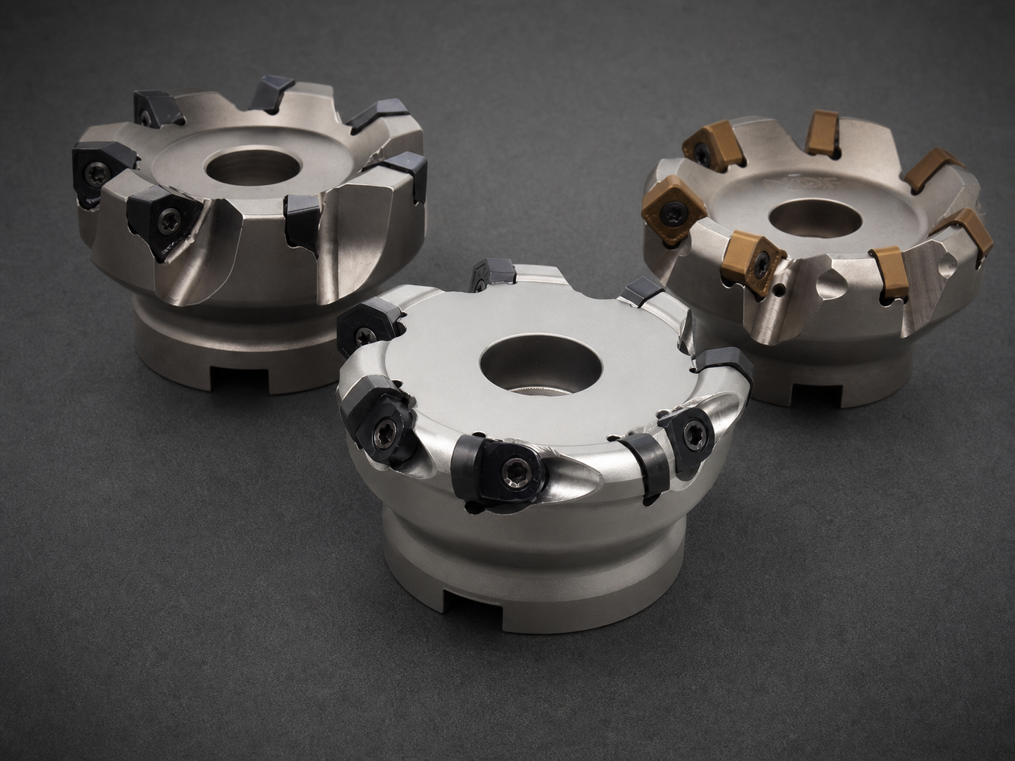
Picture the transverse section
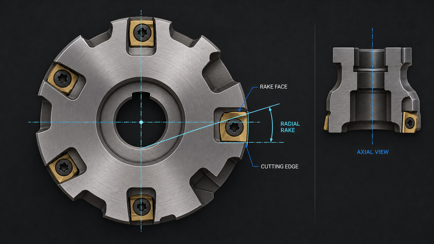
Imagine cutting the milling tool with a plane perpendicular to the cutter axis at the point where the peripheral edge is engaged. Looking into that cross-section, identify three things:
- the local cutting edge;
- the rake face over which the chip flows;
- the radial reference used by the tool manufacturer.
The angle between the rake-face direction and that defined reference is the radial rake under the maker’s convention. The exact construction of the reference and the positive/negative sign convention must come from the drawing or specification being used. Do not combine values from different catalogs until their reference conventions are confirmed.
The phrase “at the local cutting point” matters. A helical solid end mill has a three-dimensional edge, and an indexable cutter may present the insert at compound radial and axial inclinations. The relevant section must pass through the engaged edge. A photograph taken obliquely does not preserve that section and can make one surface appear steeper or flatter than it is.
This transverse view gives radial rake a distinct job. It describes the cutting-face component around the cutter circumference. Axial geometry is evaluated in a different reference section and addresses face inclination along the cutter axis. Both may act at the same edge, but they are not interchangeable numbers.
Separate nominal angle from effective cutting geometry
A nominal radial-rake value is useful only if the physical feature behind it is known. Near the edge, a hone, land or chamfer can alter the immediate contact before the chip reaches the broader rake face. The cutting material, edge preparation and wear state can therefore change local cutting behavior even when the nominal angle has not changed.
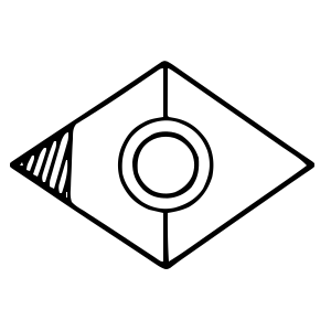
“Effective” geometry describes what the assembled, engaged cutter presents to the workpiece. For a solid tool, flute grind, helix, edge preparation and any regrind history contribute to that local shape. For an indexable tool, the cutter pocket tilts the insert while the insert top form and chipbreaker contribute their own geometry. The effective radial rake is not necessarily obvious from the insert’s flat top or nominal insert category.
That distinction prevents a common error: treating a positive or negative insert label as the radial rake of the complete cutter. Insert style can describe one design feature, while the body has both radial and axial seating angles. Verify the body-and-insert combination as a system.
Identify effective radial rake on solid and indexable cutters
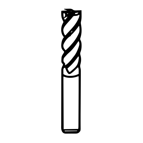
For a solid end mill, begin with the manufacturer’s sectional drawing or geometry statement. Locate the peripheral edge and the flute face in the specified transverse section. Confirm whether the published value applies to the peripheral edge, end cutting edge or another feature. A single family description may not define every diameter, flute count or application geometry.
For an indexable milling cutter, verify the body pocket, insert designation, insert orientation and chipbreaker. A replacement insert that fits the pocket mechanically may not reproduce the intended cutting geometry. Seat contamination, damaged pockets or the wrong screw/clamp condition can also alter edge position and load sharing even if the nominal rake categories match.
When no verified angle is available, do not reverse-engineer a precise value from a catalog photograph. Ask for the drawing, use a qualified inspection or tool-measurement method, or describe observed cutting behavior without assigning an unsupported number. Reground solid tools also need an approved regrind specification because flute-face changes can alter effective geometry, diameter and edge preparation together.
Follow what changes at the edge
Radial rake changes the shape and support of the cutting wedge in the transverse plane. In broad terms, moving the geometry in a more positive direction tends to create a freer shearing action with lower force and easier chip movement, while moving in a more negative direction tends to retain more material behind the edge and increase support. These are directional tendencies under matched conditions, not universal recommendations.
The force effect reaches beyond spindle load. A higher-force cutting action can increase tool deflection, workpiece displacement and fixture demand. A freer-cutting action may help a flexible setup but can leave less wedge support for interruption or impact. Grade, edge preparation, coating or surface treatment, chip load and engagement can reinforce or counter those tendencies.
This is the edge strength tradeoff in context: the nominal radial-rake direction changes material behind the edge, but carbide grade, hone or land, local wedge, interruption and load sharing determine whether the edge actually survives. A stronger-looking section can still chip under runout or chatter, while a sharper section can remain reliable in a stable, correctly loaded cut.
Chip flow also depends on flute or pocket shape and available chip space. A radial-rake change that improves shearing cannot solve a blocked flute, recutting chips or unsuitable evacuation. Likewise, a supported edge can still fail if runout makes one tooth carry most of the load.
Surface finish is an outcome of the whole process. Radial rake can influence cutting force, burr formation, built-up material and edge behavior, but finish also responds to runout, spindle condition, holder reach, feed per tooth, path, axial geometry and vibration. Treat a finish change as evidence to investigate, not proof that the angle alone is correct or wrong.
Read radial and axial rake as a pair
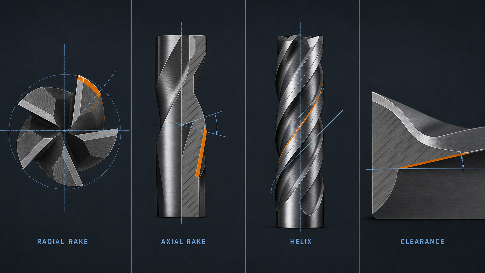
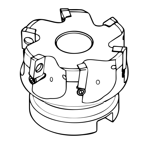
Facemilling sources illustrate why designers and tool selectors consider radial rake with axial rake. A cutter can combine positive and negative directions in the two planes to balance tangential cutting action, axial force direction, edge support, chip flow, power draw and surface behavior. The pair, not either angle alone, describes more of the assembled cutting action.
This does not mean every facemilling combination transfers to a solid end mill. Face mills often use indexable inserts, body pockets and lead angles that differ from helical solid cutters. The transferable lesson is structural: state both coordinate components and the assembled geometry before predicting force or chip behavior.
For end mills, helix can redirect force and make axial/radial effects appear coupled. Still, the helix angle is not a substitute for a published axial-rake or radial-rake specification. Use the manufacturer’s definitions rather than deriving one angle from another.
Do not confuse radial rake with nearby terms
Axial rake describes face inclination in an axial reference section through the cutter axis and local edge. It influences the axial component of cutting action and chip movement.
Helix angle describes the spiral of a flute relative to the cutter axis. It affects engagement timing, force direction and chip transport, but it does not by itself state the rake-face inclination in the transverse section.
Clearance or relief angle lies behind the edge and prevents the flank from rubbing the newly machined surface. Radial rake is on the chip-flow side of the edge.
Lead or approach angle describes how a milling edge approaches the work and changes chip shape and force direction. It can alter the result of a rake selection but is not radial rake.
Radial engagement or radial depth of cut is the width of cutter engagement in the workpiece. It is an operating parameter, not a ground angle. Similar use of the word “radial” does not make them the same quantity.
Edge preparation changes the immediate edge radius, hone or land. It may dominate initial contact even though the nominal rake behind it is unchanged.
Recognize when the drawing is insufficient
Stop treating the specification as comparable when the reference plane, sign convention or engaged edge is missing. Also stop when one source describes an insert alone and another describes the assembled cutter, or when a solid tool and indexable body are compared only by a shared positive/negative label.
A photograph-only listing is insufficient for a numerical rake claim. So is a family page that does not confirm whether geometry changes by diameter or flute count. A regrind, damaged pocket, incorrect insert or edge wear can make an original drawing incomplete for the tool currently in the spindle.
In those cases, obtain model-level information or qualify the actual tool. Do not fill the gap with a generic angle chart. The evidence package for this article contains no verified SCT model-level radial-rake drawing and no universal standard-like range, so no numerical recommendation is supplied.
Use radial rake as one verified input
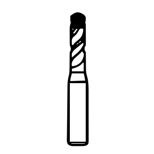
The carbide end mill can help locate candidate tool families, but it is not evidence of a particular radial-rake value. The exact item drawing and application data remain the source of geometry and cutting conditions.
Interpret radial rake inside a complete application tuple: cutter construction, material and hardness, scale or interruption, roughing or finishing, radial and axial engagement, reach, machine power, spindle/holder condition, runout, fixture and workpiece stiffness, chip space, coolant or air, dimensional tolerance and finish target.
If force or deflection is limiting, the radial-rake direction is one geometry input to evaluate with the toolmaker. If edge damage under interruption is limiting, wedge support and edge preparation become important. If chip packing is limiting, flute volume, path and evacuation may matter more than a small angle change.
Document why the angle matters in this operation. “Positive” or “negative” is not a reason by itself. A usable selection statement connects geometry to an observed constraint and names the co-variables that must remain fixed.
Verify what the geometry does in the cut
Qualify the exact tool, not the abstract angle. Record manufacturer and item number, published radial and axial geometry, solid or indexable construction, insert/body combination, edge preparation, diameter, reach, holder and measured runout. Record material condition, RPM, feed per tooth, engagement, toolpath and evacuation.
Then inspect spindle load trend, sound, chips, burrs, surface, dimensions, built-up material and every cutting edge. A geometry selected for lower force should reduce the force-related symptom without unacceptable wear or edge damage. A geometry selected for support should improve edge survival without creating unstable load, deflection or chip-control problems.
Release only the proven condition window. If the insert, body, regrind, reach, material, engagement or fixture changes, recheck the interpretation. Radial rake is a precise and useful geometry term when its section and convention are known; without them, it is only a label.