


Ball Nose vs Flat End Mill: Choose by Surface and Tool Contact
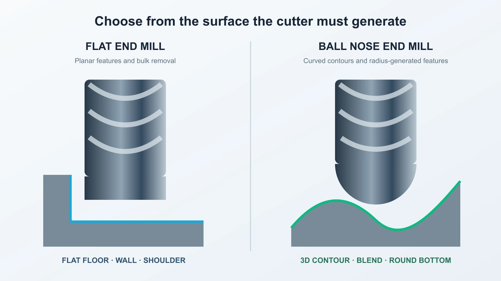
For ball nose vs flat end mill selection, choose from the surface: use a flat end mill when the cutter must generate flat floors, vertical walls, shoulders, open pockets, or remove bulk stock; use a ball nose when its radius must generate a curved 3D contour, blend, or round-bottom feature. When a part contains both types of work, rough with a flat or corner-radius tool, leave controlled stock, and finish the curved surface with a ball nose.
That distinction matters because the two tools do more than leave different shapes. They contact the work differently. The contact point on a ball nose moves as the surface slope changes, so its effective cutting diameter—and therefore the cutting speed at the edge—also changes. Tool selection, toolpath direction, and cutting data have to be considered together.
Choose from the surface the cutter must generate
Start with the finished feature, not with the cutters already in the carousel. Ask which edge geometry can generate the required surface without forcing the tool to cut in an unfavorable contact zone.
| Feature or task | Usual first choice | Why | What can change the choice |
|---|---|---|---|
| Flat floor | Flat end mill | The end geometry generates a planar surface directly | A specified floor radius, blend, or textured finish may require another finishing tool |
| Vertical wall or square shoulder | Flat end mill | Its peripheral edge can generate the wall while the end addresses the floor | A corner-radius tool may be preferred when edge strength or a fillet is part of the process |
| Open pocket or bulk roughing | Flat or corner-radius end mill | It can remove stock without relying on the slow center region of a ball | Complex remaining stock or limited access may require staged tools and rest machining |
| Sculpted 3D surface | Ball nose end mill | The continuous tip radius follows changing slopes without a sharp end corner | A bull nose may rough or semi-finish broad, shallow regions before ball-nose finishing |
| Round-bottom groove | Ball nose end mill sized to the required form | The tip radius can generate the bottom profile | Deep reach, chip packing, or a nonstandard radius may make a specialty cutter or another process more suitable |
| Blend or internal radius | Ball nose or an appropriate corner-radius tool | A radius-bearing edge can generate the transition | The exact geometry, access, and adjoining surfaces decide which radius tool fits |
| Deep narrow feature | Usually a staged process | A rigid tool can remove most stock before the radius is finished | Reach, holder clearance, deflection, evacuation, and the required bottom form may change the entire method |
The “usual first choice” column is a starting point, not a catalog rule. A cutter that can physically enter a feature is not automatically the cutter that should perform every operation inside it.
What changes at the cutting edge
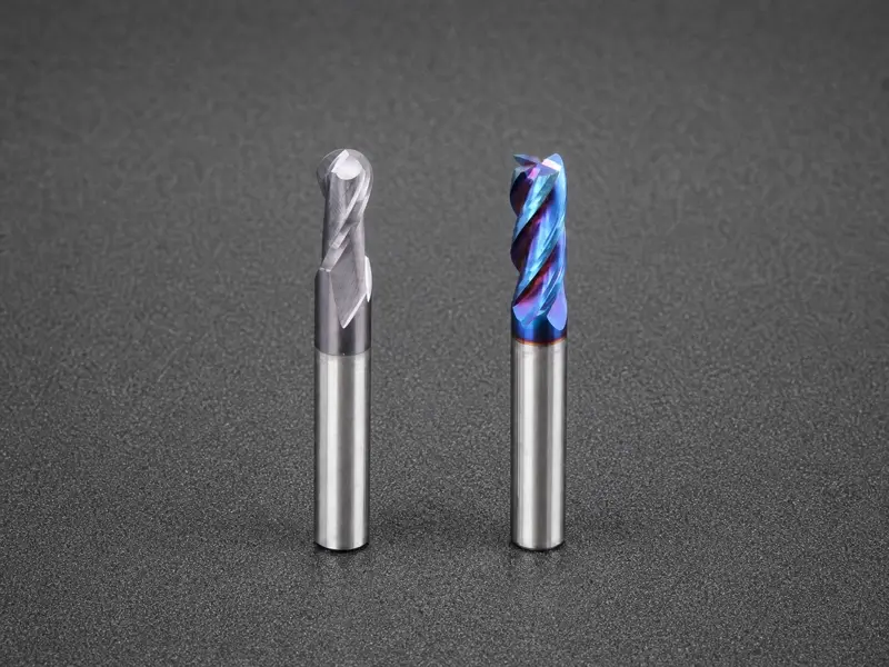
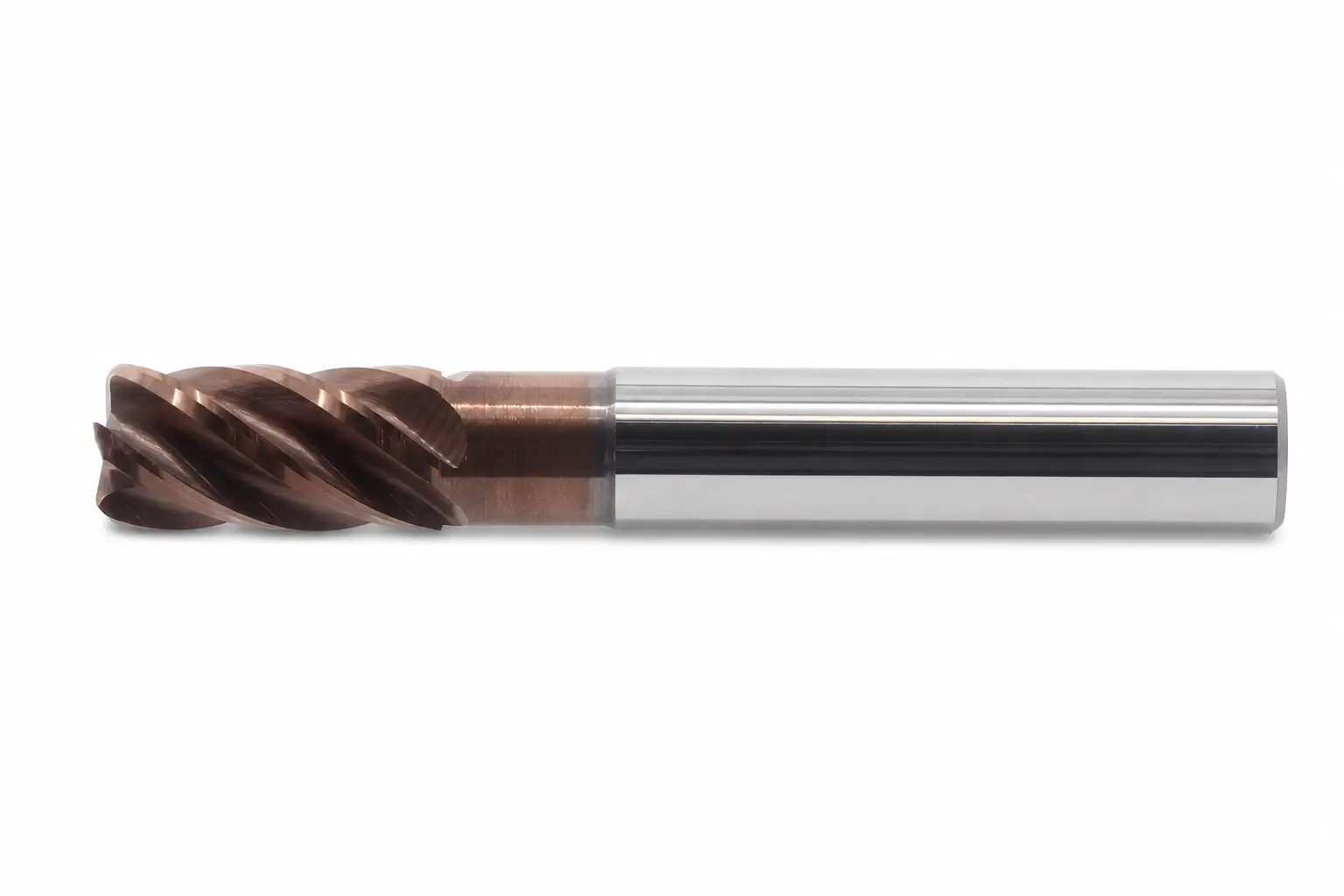
A flat end mill uses its peripheral cutting edges for walls and side cutting, while its end geometry generates the floor. This makes it a natural fit for prismatic features: flats, shoulders, steps, and pockets. “Flat” describes the surface it is intended to generate; it does not mean every point across the tool face cuts identically or that every manufacturer uses identical center geometry.
A ball nose replaces the square end corner with a continuous hemispherical profile. That rounded profile can touch surfaces whose slopes change continuously, which is why it is common in dies, molds, freeform parts, and blended transitions. The same geometry that gives it access to those contours also creates its main process limitation: the cutting condition depends on where the work meets the ball.
A corner-radius or bull-nose end mill sits between these choices. It retains a substantial flat or near-flat end region but protects the outer corner with a radius. It is useful for many roughing and semi-finishing operations, but it is not interchangeable with a full ball nose. A small corner radius cannot generate the same continuously curved form as a hemispherical tip.
The ball does not cut at one effective diameter
The nominal diameter printed on a ball-nose tool describes its maximum diameter. It does not describe the diameter at every possible contact point on the ball. The relevant effective diameter depends on where the work contacts the hemispherical tip.
Imagine horizontal circles drawn around the tip at different heights. Near the tool’s full diameter, the circle is large. Closer to the center of the tip, it becomes progressively smaller. All of those circles rotate at the same spindle speed, but a smaller circle travels a shorter distance per revolution. At the exact center, the effective radius approaches zero, so the local surface speed also approaches zero.
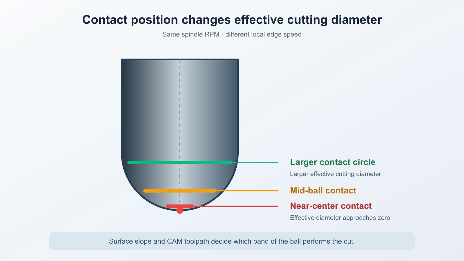
This is why a ball nose cutting almost directly on its center can rub, heat the work, smear material, or form a poor chip even when the nominal tool diameter and programmed RPM appear reasonable. Move the contact farther up the ball and the effective cutting diameter increases. On a 3D surface, that contact point may move continuously as the cutter crosses flats, slopes, and near-vertical regions.
The toolpath therefore affects cutting mechanics. A path that repeatedly drives the tool center across a shallow area may behave differently from a path that keeps contact on the side of the ball. Machine RPM limits also matter: a small effective diameter may call for a speed the spindle cannot provide. The correct response is not to publish one universal compensation value, but to identify the expected contact zone and use the toolmaker’s data and CAM strategy for that condition.
Choose the cutter sequence, not just the cutter
Using a ball nose for an entire cavity can look efficient because it avoids a tool change. In practice, the saved tool change may be much smaller than the time lost by asking a finishing geometry to remove bulk stock.
Shop discussions of deep, narrow slot milling illustrate why the bottom radius and the bulk-removal step should be treated as separate problems. A more robust sequence is often:
- Remove most material with a rigid flat or corner-radius tool.
- Leave a controlled and reasonably uniform finishing allowance on the curved surfaces.
- Rest-machine areas the rougher could not reach if necessary.
- Use the ball nose only where its radius is needed to generate the final form.
This sequence lets each cutter work in the role its geometry supports. The rougher handles high-volume removal without forcing a ball tip through extensive center contact. The finisher sees predictable stock instead of alternating between air, heavy engagement, and unexpected corners. It can also reduce deflection and make the final toolpath easier to prove out.
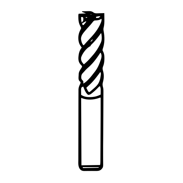
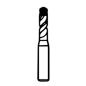
The sequence still has to respect the actual cutter geometry, reach, and application data. The carbide end mill is a navigation point for identifying candidate tool families; verify the selected cutter’s dimensions and manufacturer recommendations before programming it.
A separate finishing tool is especially valuable when the part combines a large pocket with one small bottom radius or a localized 3D contour. Conversely, if nearly the entire surface is curved and stock has already been reduced by a previous process, a ball-nose semi-finishing and finishing sequence may be more appropriate than forcing a flat tool into geometry it cannot generate.
Match the toolpath to the feature
Flat floors, shoulders, and open pockets
For a planar floor, a flat end mill generates the intended surface directly. Its peripheral edge also gives a clear way to control walls and shoulders. A ball nose used on the same floor leaves a curved contact profile; producing an acceptably flat-looking surface then depends on many closely spaced passes, and center contact can create rubbing rather than effective cutting.
In an open pocket, also consider how the tool enters, how much of its diameter is engaged, and where chips can escape. A flat end mill is not automatically safe at full-width engagement, but its geometry is normally the more logical starting point for bulk pocketing. Use CAM verification and manufacturer data to choose entry, radial engagement, axial engagement, and stock allowance.
Sculpted surfaces and changing slopes
A ball nose can follow a changing surface normal without presenting a sharp corner to the part. Surface finish then depends on more than the tool’s nominal diameter. Stepover controls the cusp or scallop left between adjacent passes, while the local slope controls where the cutter contacts the ball. Toolpath direction can shift contact away from or toward the slow center region.
For this reason, a single finishing strategy may not suit every region of a complex part. Shallow areas, steep walls, and transition zones may benefit from different path families or machining directions. The goal is a consistent residual pattern and stable edge contact, not merely a uniform XY stepover copied across the entire model.
Stock condition matters too. If roughing leaves irregular cusps or isolated heavy areas, the finishing tool receives a changing load. A semi-finishing pass can normalize the stock before the final pass, making the surface finish more predictable without pretending that it guarantees a particular result.
Round-bottom and deep narrow features
A required round bottom may make a ball nose the correct finishing geometry, but it does not follow that the ball nose should excavate the complete slot. In a deep, narrow feature, a long-reach cutter has less resistance to deflection, the holder may limit access, and chips have a difficult exit path. The ball center may also remain buried in material for much of the cut.
Consider removing accessible stock with a shorter, more rigid flat tool first, then extending only as far as needed with the finishing cutter. Check flute length separately from overall reach: a tool may reach the bottom but still rub with its neck or shank. Verify that chips can leave the feature and that coolant or air reaches the cutting zone rather than compacting chips farther down.
If the feature demands extreme reach, a very narrow width, or a special bottom form, the right answer may be a specialty cutter, drilling operation, EDM, or a redesigned process. “Ball nose fits the radius” is only one requirement.
Do not transfer parameters by nominal diameter
Two cutters with the same nominal diameter do not necessarily use the same starting RPM and feed. For the ball nose, the relevant contact diameter may be smaller than the nominal diameter. The tool may also be performing a light finishing pass while the flat end mill performed roughing with a different engagement and chip thickness.
Build the starting condition from the selected tool’s data and the actual operation. At minimum, account for:
- workpiece material and condition;
- cutter substrate, geometry, coating, diameter, and flute count;
- expected contact location on a ball nose;
- radial and axial engagement;
- roughing stock or finishing allowance;
- toolpath direction and stepover;
- stickout, holder condition, and runout;
- spindle-speed, feed, power, and acceleration limits;
- chip evacuation and coolant strategy.
If the calculated speed exceeds the machine’s usable range, do not simply cap RPM and leave the feed unchanged. Recalculate the commanded feed and check whether the resulting edge condition remains workable. Prove the setup under controlled conditions before releasing it to a valuable part.
Read the surface and tool before changing every number
When the result is poor, changing RPM, feed, stepover, and depth simultaneously destroys the evidence. Read the symptom first, verify the likely mechanism, then change one controlled variable.
- Flat spots or the wrong form: Check whether the selected edge geometry can generate the CAD surface and whether the CAM tool definition matches the physical cutter. Correct the geometry or toolpath before tuning cutting data.
- Rubbing, discoloration, or heat near the ball tip: Inspect where the surface contacts the ball and whether the path crosses the tool center. Reorient the path or change the tool/process so a more effective edge region performs the cut.
- Built-up material on the edge: Verify material behavior, edge condition, chip formation, lubrication, and evacuation. Do not assume “ball nose” alone is the root cause.
- Visible scallops: Confirm actual tool radius, stepover, surface slope, and tool deflection. Reduce or redistribute the residual pattern only after confirming that the programmed tool matches the cutter.
- Chatter or tapered walls: Inspect stickout, holder condition, runout, engagement, and remaining stock. A shorter or more rigid roughing step may solve what parameter trimming cannot.
- Chip packing in a deep feature: Stop recutting trapped chips. Improve evacuation, reduce the amount of buried cutting, or revise the sequence.
- Premature wear in one area of the ball: Map the wear to the contact zone. A path that concentrates all cutting on a narrow band may need a different orientation or a different finishing strategy.
Release the setup when these conditions are known
Before the first production part, the setup owner should be able to state:
- which surfaces are planar, which are radius-generated, and which are transitional;
- the role of each cutter—roughing, rest machining, semi-finishing, or finishing;
- the stock each finishing pass is expected to encounter;
- the expected contact zone on the ball nose;
- the source and applicable conditions for the starting cutting data;
- the toolpath direction, stepover logic, and entry method;
- actual stickout, holder condition, and runout status;
- how chips leave the deepest or most enclosed region;
- which machine limit governs the command;
- what the proof cut showed on the surface, chips, sound, load, and cutting edge.
If any of those answers is unknown, the operation is not ready because “ball nose versus flat end mill” has not yet been reduced to a specific surface, contact condition, and process role.