



Blind Holes: The Expert Guide to Drilling and Tapping
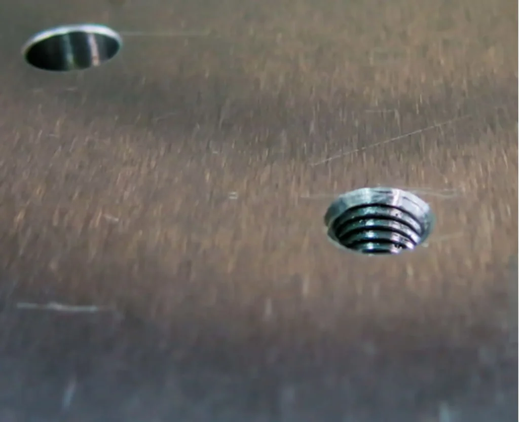
A blind hole is a hole that does not break through the opposite side of a workpiece. You find them in engines and electronics where a smooth back surface is needed. They act as a pocket for screws or pins. This guide shows you how to drill and tap them without breaking tools.
Contents
What is a Blind Hole?
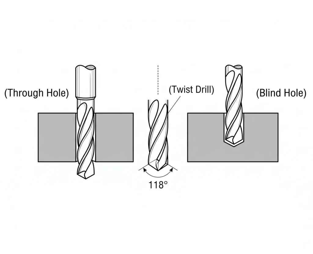
First, you need to understand the basics. It just means a hole with a bottom. Unlike a through hole, you cannot see the light at the end of the tunnel. Why do we use them? It is a helpful way to keep the back of your part clean and untouched. Do you know? Most engine blocks are full of these. They allow for strong clamping without leaks.
Blind Hole vs Through Hole
A blind hole is a machined hole that does not pass completely through the workpiece. It has a controlled bottom depth, unlike a through hole, which opens on the opposite side of the part. In CNC machining, blind holes are common in threaded parts, fixture holes, hydraulic components, molds, and assemblies where the back side of the part must remain sealed or clean.
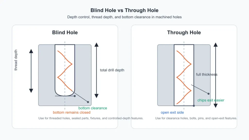
| Feature | Blind Hole | Through Hole |
|---|---|---|
| Opening | One side only | Passes through the part |
| Depth control | Critical | Less critical |
| Chip evacuation | More difficult | Easier |
| Common risk | Bottoming out, chip packing, broken taps | Burrs or exit-side damage |
| Typical use | Threaded holes, sealed parts, fixtures | Bolts, pins, clearance holes |
How to Drill Blind Holes
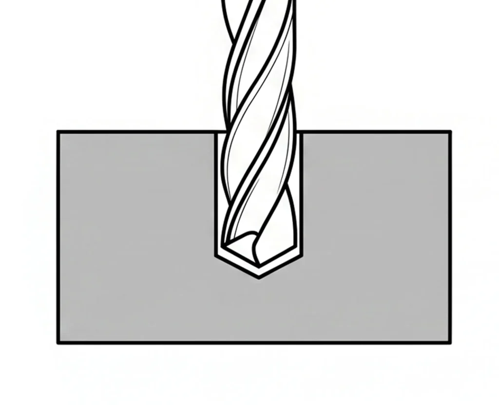
Originally, you might think it is just like any other drilling job. Not so great. You should generally avoid just plunging in. First, of course, you must mark your center point accurately.
Choose your drill bit for the material and hole specification. A conventional twist drill leaves a conical bottom, so distinguish full-diameter depth from drill-tip depth. Set and verify the depth reference; select a CNC cycle recommended for the drill rather than assuming every blind hole requires G83.
Where the tool requires peck drilling, program the retraction and chip-clearance sequence according to the tool and machine instructions. Other drills are intended for continuous feed with through-tool coolant. Repeated re-entry is not automatically beneficial.
Managing Blind Hole Depth
How deep should you go? This can be a useful question when you are designing a part. In terms of engineering, you need to leave room at the bottom. You should be able to fit the bolt and some extra space.
- Total depth:The distance from the top to the very tip of the drill.
- Effective depth:The usable part of the hole that has the full diameter.
- Thread depth: Specify the required length of full-form usable thread, separately from tap travel and incomplete lead threads.
Allow clearance for the screw end and for the selected tapping process while preserving the required remaining wall thickness. Two or three pitches is not a universal clearance rule; determine the allowance from the drawing, tap geometry, and process.
Drill Depth, Thread Depth, and Bottom Clearance
Distinguish drill-tip depth, full-diameter bore depth, full-form thread depth, and tap travel. A pointed drill extends below the full-diameter bore. Tap chamfer length and any projecting centre or nose also require allowance.
Specify clearance below the required full-form thread for the chosen tap geometry and chip-removal process, plus screw-end clearance where applicable. Do not treat the bottom as unlimited chip storage. Verify both usable depth and remaining wall thickness with appropriate inspection.
Tapping Blind Holes
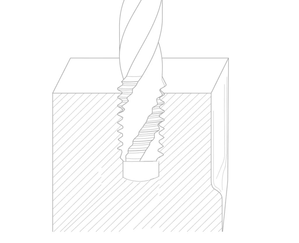
Spiral-flute cutting taps can carry chips back toward the entry and are commonly used for blind holes in suitable materials. Select flute design and chamfer for the material and depth; short-chipping materials and forming taps may require different choices.
Next, choose your tap style.
- Taper Taps: A long chamfer needs additional axial clearance and may not produce full threads near the bottom.
- Plug Taps: The chamfer leaves incomplete threads near the end of the cut; allow for its actual length.
- Bottoming Taps: A short chamfer allows full threads closer to the bottom, but still requires clearance for the chamfer and any projecting tip.
Use the specified tapping lubricant or coolant and an appropriate speed. During hand tapping, stop if resistance becomes abnormal. CNC tapping requires the correct spindle/feed synchronisation and programmed travel; operator feel is not a substitute for process control.
Tap Drill Size and Pilot Hole Preparation
Choose the pre-hole diameter from data for the thread size, tolerance, material, and tap type. Cutting and forming taps need different pre-hole sizes. Provide adequate full-diameter depth and tool clearance without breaking through the remaining wall.
Check drilling and tapping depths independently. Spiral-flute cutting taps can help remove long chips from blind holes. A suitable short-chamfer tap can produce full threads closer to the bottom, but still needs clearance and is not always a separate finishing operation.
For high-value parts where broken taps are unacceptable, carbide thread mills can be a useful alternative to conventional tapping.
Precision with a Blind Hole Cutter
Use a flat-bottom drill or other tool specifically designed for the required bottom geometry. Flatness and surface finish must meet the component drawing; a flat bottom is not necessary for every spring or bearing feature.
Choose a sequence compatible with the selected tool. Some tools can drill from solid, while others finish a prepared hole. Confirm permitted entry conditions and inspect the required bottom geometry.
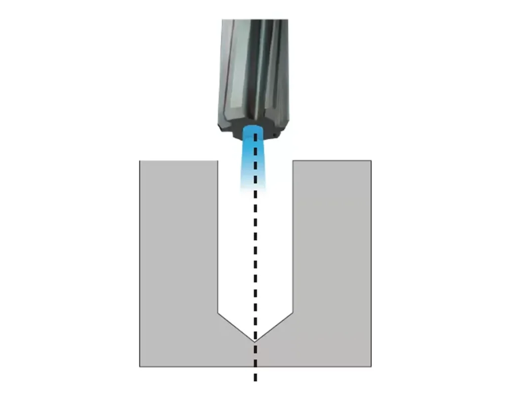
PCD reamers and carbide reamers can finish suitable pre-drilled bores when tool material, geometry, allowance, and bottom clearance are appropriate. Reaming controls bore size and finish; it does not by itself establish thread quality.
Measuring Blind Holes
Select a measuring instrument for the specific feature: bore diameter, full-diameter depth, bottom profile, or thread size and depth. Not every blind-hole gage expands inside the bore.
- Blind Hole Micrometer: A suitable internal micrometer measures diameter within its range; confirm its ability to reach the required location near the bottom.
- Blind Hole Depth Gage: Use a suitable contact shape and datum to distinguish tip depth from full-diameter depth.
- Thread Plug Gage: Use the specified GO/NO-GO inspection for thread acceptance, and a suitable depth feature or separate method to verify full-form thread depth.
Until then, you might just guess. Do not do that. Inspect blind holes every time you finish a batch. Later, you might find that a small change in tool wear made the holes too shallow.
CNC and Milling Strategies
A suitable end mill can machine a blind pocket or bore using an approved plunging or interpolation strategy. Tool end geometry and the path determine bottom shape; a flat bottom is not automatic. Deep, narrow holes may favour drilling.
For a helical blind hole tap, confirm the actual tool type and manufacturer instructions. Program tapping with the correct spindle/feed synchronisation and travel limits. Use simulation and a controlled prove-out procedure; a dry run alone does not validate cutting conditions.
Use an approved coolant and chip-removal system within tool and machine pressure limits. Monitor wear and chip evacuation for the actual material; neither high-pressure coolant nor an air blast is a universal solution.
Material Specifics
Aluminum alloys can adhere to cutting edges; select tap geometry and lubrication accordingly, including for an M6 thread. Steel requirements vary by grade and hardness. Cobalt-alloyed high-speed steel is a type of HSS, not a separate alternative to it.
Also, think about how the metal acts. Some metals are soft. They might deform if the hole is too close to the edge. Note that you want to always want enough wall thickness. If the wall is too thin, the pressure of drilling blind holes might bulge the outside of your part.
Common Problems
What happens when things go wrong? It is usually one of three things:
- Chip Packing:The hole fills with metal. The drill cannot go deeper and snaps.
- Bottoming Out:The tap strikes the floor.
- Overheating:The drill gets too hot because the coolant cannot reach the bottom.
So, aside from the tools, your process is what makes it work. Further, always keep your tools sharp. A dull drill creates more heat and more trouble.
Troubleshooting Tips
Stop the machine and follow the applicable isolation procedure before investigating a broken tap or packed chips. Use a qualified removal method appropriate to the tool and part; an extractor is not guaranteed to work. Any vacuum equipment must be suitable for the chips, coolant, and material hazards.
Final Inspection
Clean the hole using an approved method before inspection. Do not assume safety glasses alone make compressed-air cleaning safe. Verify bore dimensions, required full-form thread depth, and thread acceptance with the specified instruments and gages.
At the onset, this might seem like a lot of work for a simple hole. But the details decide if your part is a success or scrap. Use the right blind hole depth gage and take your time. This often just separates the pros from the amateurs.
Conclusion
Blind holes are vital for clean, strong designs in machining. You must manage depth and chip removal to avoid breaking tools. Using the right spiral taps and gages ensures your threads are accurate. Always prioritize clearing chips and checking your measurements to keep your production smooth and your parts high quality.
FAQs
What makes a blind hole different from a through hole?
A blind hole has a bottom while a through hole goes all the way through the part. This often just means you cannot see light at the end of it. Do you know? This makes removing metal chips much harder. Consequently, you must be more careful with your tools so they do not snap.
How do you calculate blind hole depth?
Start with the required screw engagement and full-form thread depth. Add the selected tap chamfer and tip allowance, process clearance, and drill-point allowance while maintaining the specified wall thickness. A deeper hole is not automatically safer.
Can you use a standard tap for blind holes?
Select tap geometry for chip form, material, and required full-thread depth. Spiral-flute cutting taps often suit blind holes with long chips; a long taper chamfer requires more clearance. Straight-flute or forming taps can be appropriate in other applications.
What is the best way to measure a blind hole?
Use suitable instruments for diameter and depth, with contact geometry that matches the feature being measured. Check threads with the specified gages and verify full-form thread depth separately where necessary; no single instrument establishes every hole dimension.
Why do drills and taps break in these holes?
Breakage can result from packed chips, inadequate lubrication, excessive torque, misalignment, incorrect synchronisation, or insufficient bottom clearance. Correct the cause and programmed travel; simply slowing near the bottom cannot prevent a collision, and tapping feed must remain matched to spindle speed.