Skip to content
CNC Router Feed Rate: Calculate Feed, RPM and Depth-of-Cut Trade-offs
Calculate CNC router feed rate by multiplying spindle RPM, the number of cutting edges and the applicable chip load. Then check whether the router, cutter and workholding can support that feed at the intended depth of cut. The calculation is a starting point; it cannot choose a suitable chip load for an unidentified material or bit.
For a new setup, use the tool manufacturer’s guidance for the material, diameter and geometry. Work through the calculation below, identify the machine’s limiting condition, and test one change at a time. This is more useful than copying a feed number from another router.
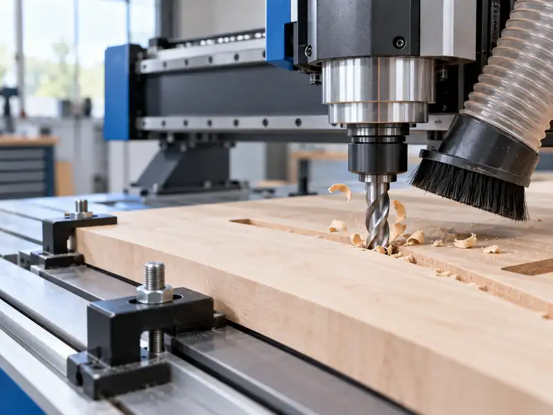
How to calculate CNC router feed rate
The basic relationship is:
feed rate = RPM × cutting edges × chip load
Rearrange it to check an existing setting:
chip load = feed rate / (RPM × cutting edges)
With feed in mm/min and speed in revolutions per minute, the result is mm per cutting edge. With feed in inches/min, it is inches per cutting edge. Check that a controller displaying inches per second is not being read as inches per minute; multiply inches per second by 60 to obtain inches per minute. Use the manufacturer’s cutting-edge count, usually the flute count.
This calculation gives the nominal feed per cutting edge, commonly called chip load in router guidance. It is not a measurement of every chip produced: engagement and unequal edge loading still affect the cut. Adding flutes or raising RPM while holding feed constant reduces this calculated value.
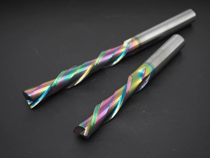
A worked example, then a machine feed limit
The following numbers are assumed for arithmetic only, not recommended settings for wood, plastic or a particular cutter. Suppose a two-edge tool runs at 18,000 RPM and the programmed feed is 3,600 mm/min:
chip load = 3,600 / (18,000 × 2) = 0.100 mm per edge
Now suppose the machine can sustain only 2,400 mm/min in this operation. At the same RPM and edge count:
chip load = 2,400 / (18,000 × 2) ≈ 0.067 mm per edge
The lower feed has changed the calculated chip load, even though the spindle setting is unchanged. To retain the original assumed 0.100 mm per edge at that feed, the arithmetic gives:
RPM = 2,400 / (2 × 0.100) = 12,000 RPM
That is a calculation to evaluate, not an instruction to run at 12,000 RPM. Check the tool’s permitted speed, the material’s cutting-speed guidance and the spindle’s torque/power behavior before testing it. If the calculated combination falls outside those conditions, revisit the tool or cutting strategy instead of forcing the numbers to fit.
What a feed-limited router changes when RPM comes down
Reducing RPM at a fixed feed increases nominal chip load. It may help when the original combination produces too little chip load, but it is not an automatic cure for heat or dust. The spindle may have less usable torque or power at the new speed, and the resulting cutting speed may not suit the tool or material.
In plastic routing, chip formation and evacuation help carry heat away from the cutting zone. When feed is limited, evaluate spindle speed together with the applicable tool geometry and material. That relationship does not establish a universal setting for every routed material.
Use actual operating RPM when it can be measured safely through the machine’s approved method. A dial setting may differ from the speed maintained under load. An inaccurate RPM input can hide the feed-to-speed relationship you are trying to control.
How router bit depth of cut affects feed selection
Depth of cut does not appear in the feed formula. If feed, RPM and edge count stay the same, its calculated chip load stays the same even when you make a deeper pass. That does not mean the deeper pass places the same demand on the tool and machine. Engagement, evacuation, power and workholding still matter.
Before increasing pass depth, check the bit manufacturer’s depth guidance for that tool and material, and whether its chip-load recommendation needs adjustment at the proposed depth. Recalculate feed if the applicable chip-load target changes. Do not assume that a general chart remains valid at any depth, or apply a fixed diameter multiplier to every router bit.
If the deeper cut produces rising load, deflection or poor evacuation, return to the last stable setup before the next test. A shallower pass may be a more appropriate change than slowing feed alone, which also reduces chip load at unchanged RPM. Compare one change at a time; a smaller chip is not proof of a safer cut.
Use the symptom to choose the first check
Symptoms help route an inspection, but do not establish a root cause. Before changing a parameter, separate a feed/RPM mismatch from a mechanical or evacuation problem.
| What you observe | First check | What the result changes |
|---|---|---|
| Fine dust with heat or a rubbing-like finish | Verify actual feed, RPM and edge count against the applicable tool guidance; inspect edge condition. | If the ratio is unsuitable, evaluate a bounded parameter change. Do not assume every dusty cut has the same cause. |
| Chips trapped or recut in a blind slot | Check tool direction, slot openness and extraction or directed air. | A downcut spiral can drive chips back into a blind slot. Correct the chip path before chasing the feed number. |
| Finish or depth varies, or marks repeat with tool rotation | Inspect collet/tool concentricity, workholding, part movement and machine condition. | Correct movement or unequal edge engagement; feed arithmetic cannot repair either. |
| Rising force, deflection or unstable cutting | Check chip load and engagement against the tool, machine power and workholding limits. | Stop an unsafe test and return to a stable setup before changing feed, speed or pass depth. |
Stop the machine and follow its isolation procedure before inspecting or reseating a tool, collet or workpiece. A loose part or unsafe cut takes priority over a parameter experiment.
Run a one-variable test that can teach you something
- Record the material, tool diameter and geometry, cutting-edge count, feed and RPM. Include actual RPM where safely available, engagement, depth of cut, extraction and workholding.
- Inspect the tool and collet seating, concentricity, hold-down and chip path. Correct an obvious mechanical or evacuation problem before compensating with feed.
- Choose one bounded change within the applicable tool and machine guidance. Keep the other settings fixed so you can tell what caused the result.
- Make a controlled test cut in the actual material. Compare chip form, heat, finish, sound, load and tool condition. Stop if the part moves or the cut becomes unstable; do not continue just to find a limit.
- Keep the change only if it improves the intended outcome without creating a new problem. Otherwise return to the baseline and evaluate the next change.
Save the setup and the result together. A useful record says which tool, material, depth and machine condition produced an acceptable cut—not just which feed number was entered.