Skip to content
Drill Bit vs Reamer: Choose by Hole-Making Stage
For drill bit vs reamer selection, the tools usually belong to different stages. Use a drill to create the hole and remove most of the material. Add a reamer when a suitable existing hole still needs a controlled finishing cut to meet its final size or surface requirement. If the hole is in the wrong location or has geometry that a guided tool will simply follow, correct it before reaming, often by boring or by improving the drilling process.
The decision should come from the drawing, assembly function, and demonstrated process capability. A drill that produces one acceptable hole is not automatically a stable drill-to-size process. A reamer is not automatically necessary just because a tolerance appears tight. Measure what drilling actually produces, identify the remaining error, and then choose the operation that can address that error.
One hole, two different jobs
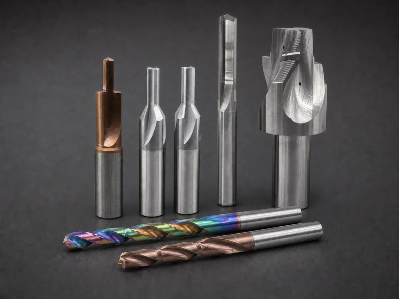
A drill bit is a hole-making tool. Its point initiates the cut, its cutting lips remove material, and its flutes provide a path for chips. In most drill-and-ream processes, drilling establishes the hole path and removes nearly all of the stock.
A reamer is a hole-finishing tool. It enters an existing hole and removes a smaller, controlled amount of material with multiple cutting edges. Its lead performs the cutting while the body and margins help guide the tool. The practical distinction is also reflected in this overview of MIT drill-press guide: drilling creates the initial hole, while reaming modifies an existing one.
That makes “reamer versus drill” the wrong mental model for many jobs. The actual choice is among process routes:
- drill directly to final size;
- drill undersize, then ream to final size;
- drill, correct the hole by boring or another operation, then finish as required.
The third route matters because drilling, boring, and reaming do not own the same errors. A reamer can improve an appropriate pre-hole, but it should not be assigned every dimensional, geometric, and location requirement simply because it is associated with precision holes.
Decide from the functional requirement, not the tool label
Begin with what the hole must do. A clearance hole for a noncritical fastener, a dowel hole, a hydraulic bore, and a guide hole can have the same nominal diameter while demanding very different control of fit, surface condition, roundness, straightness, and location.
Translate the requirement into features the process can verify:
- acceptable final hole size across the full usable depth;
- the fit or functional relationship with the mating component;
- surface finish or sealing behavior where relevant;
- location relative to datums or other features;
- straightness, taper, roundness, or cylindricity where the drawing controls them;
- whether the hole is through, blind, interrupted, or crosses another feature;
- how many conforming holes must be produced before the tool is changed;
- how the result will be measured.
Then establish what drilling alone can do in the actual setup. Tool geometry and material matter, but so do machine condition, spindle and holder runout, entry surface, fixture rigidity, chip evacuation, coolant delivery, drill wear, and the way the hole is inspected. A shop account of drilling and hole-tolerance variation is a useful reminder that worn bearings and ordinary twist-drill behavior can produce oversize holes; the nominal tool diameter does not prove the finished result.
Use drilling alone when measured output repeatedly satisfies the functional requirement. Use drill-and-ream when drilling establishes a suitable path but does not provide the required final sizing consistency or surface condition. Add a correction stage when the drilled hole is misplaced, significantly out of line, or otherwise unsuitable for a guided finishing tool.
This is a capability decision, not a prestige ranking. In a human-reviewed discussion about holding a close tolerance with a small drill, experienced machinists disagreed about whether the drill might hit the specified range under the stated conditions. That disagreement is the point: theoretical possibility and reliable production capability are different questions.
The pre-hole is part of the reaming operation
A reamer does not begin its work at the finished diameter. Its result depends on the hole delivered by the previous operation. The pre-hole therefore has to be specified as an input to reaming, not treated as an incidental rough feature.
The first input is stock allowance: the material intentionally left for the reamer to remove. Too much material can overload the cutting lead, increase force, worsen chip control, and encourage deflection or chatter. Too little can prevent the edges from cutting cleanly, leading to rubbing, heat, glazing, or accelerated wear. The correct allowance is not one universal percentage or diameter difference. It changes with reamer type and diameter, work material, hole depth, interruption, machine and holder condition, coolant, and the toolmaker’s application data.
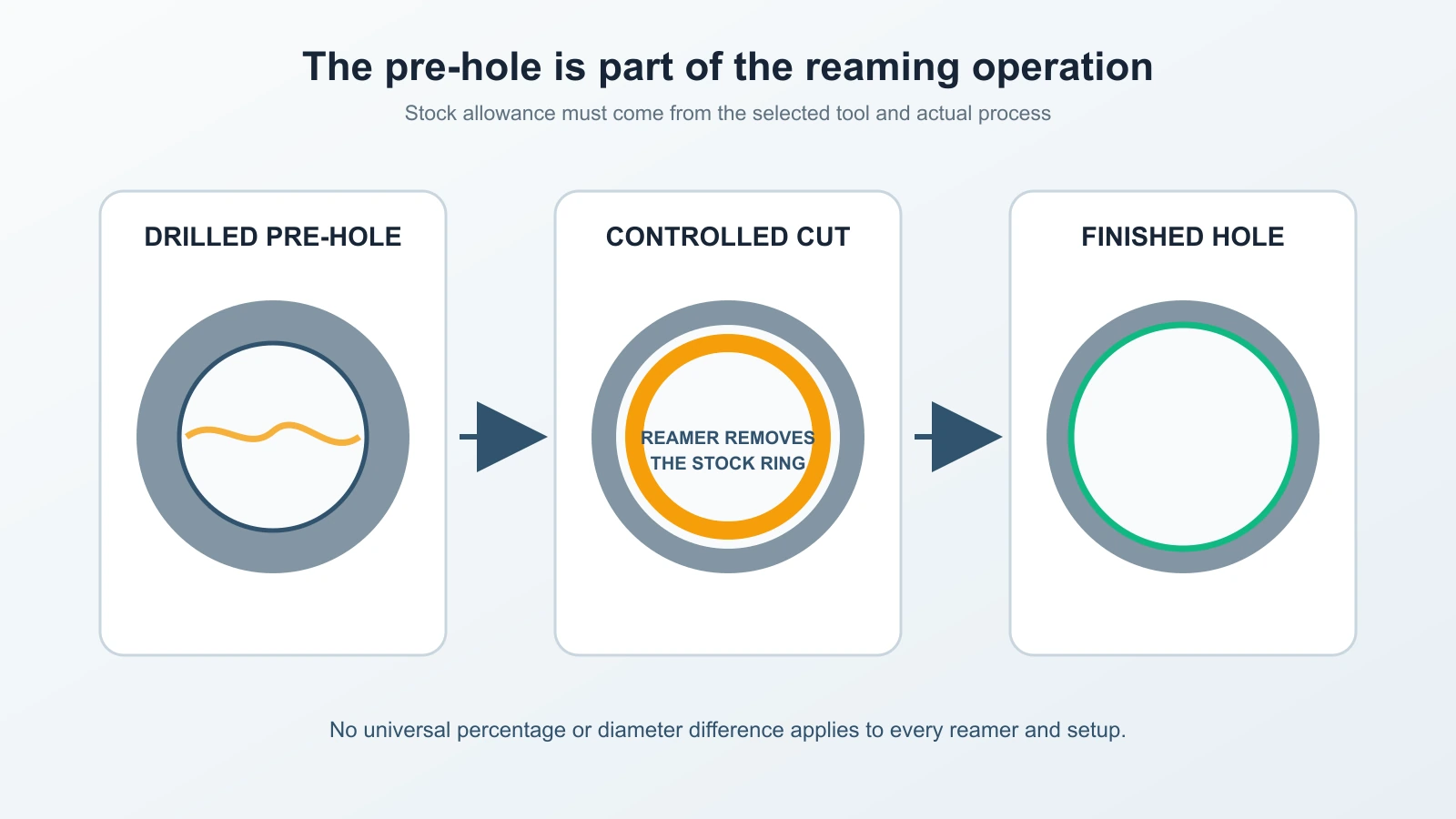
The pre-hole must also provide a usable path. Check:
- diameter and diameter consistency before reaming;
- location and alignment relative to the intended axis;
- taper, straightness, lobing, and damage from chip recutting;
- entry condition, including chamfer or burrs where applicable;
- available lead clearance at the bottom or exit;
- whether the hole crosses slots, keyways, or other interruptions;
- whether chips can move in the intended direction;
- whether the setup remains clamped in the same relationship between operations.
If the pre-hole varies substantially, the reamer does not receive a constant cutting load. It may cut heavily in one region, rub in another, or be pushed sideways by the existing path. Final inspection then reveals a “reaming problem” whose origin was actually drilling, fixturing, or tool alignment.
For that reason, the drilled size should not be chosen merely by subtracting an arbitrary number from the final diameter. Select it with the specific reamer data, verify what the drill produces rather than relying only on its marked diameter, and inspect representative holes before releasing the combined process.
What a reamer can improve and what it follows
With a suitable pre-hole, a reamer can make the final diameter more consistent and improve the interior surface by taking a controlled finishing cut. Multiple edges share the cut, and the guided body helps stabilize the tool within the existing hole. Those characteristics explain why reaming is often selected for fit-critical holes and for cases where drilling alone leaves an unacceptable surface finish.
The guidance is also a boundary. A reamer tends to follow the path it is given. It is not a general-purpose tool for moving a hole center, correcting a large angular error, or removing enough material to erase severe pre-hole geometry. The exact correction capability depends on tool design and setup, but planning should assume that upstream location errors need an upstream remedy.
Boring belongs in this discussion because a single-point boring operation can deliberately establish or correct the path and diameter of an existing hole. It can be the appropriate intermediate step when the hole must be trued to a machine axis or located more accurately before a subsequent finish operation. Boring is not automatically required before every reamer, and reaming is not automatically required after every boring operation. Each stage must close a defined capability gap.
Ask what the remaining nonconformance is:
- If the hole is correctly located and straight enough but the diameter or surface condition is inconsistent, reaming may address the gap.
- If the hole axis or location is wrong, correct the geometry or the drilling process before expecting reaming to help.
- If the pre-hole has variable stock around its circumference, determine whether the reamer can enter without being forced off line.
- If drilling already meets every functional and inspection requirement, omit the additional operation.
Plan the handoff from drill to reamer
The handoff should contain a decision gate, not just a tool change. Drill the pre-hole, verify the features that govern reaming, and route the part according to what that inspection shows.
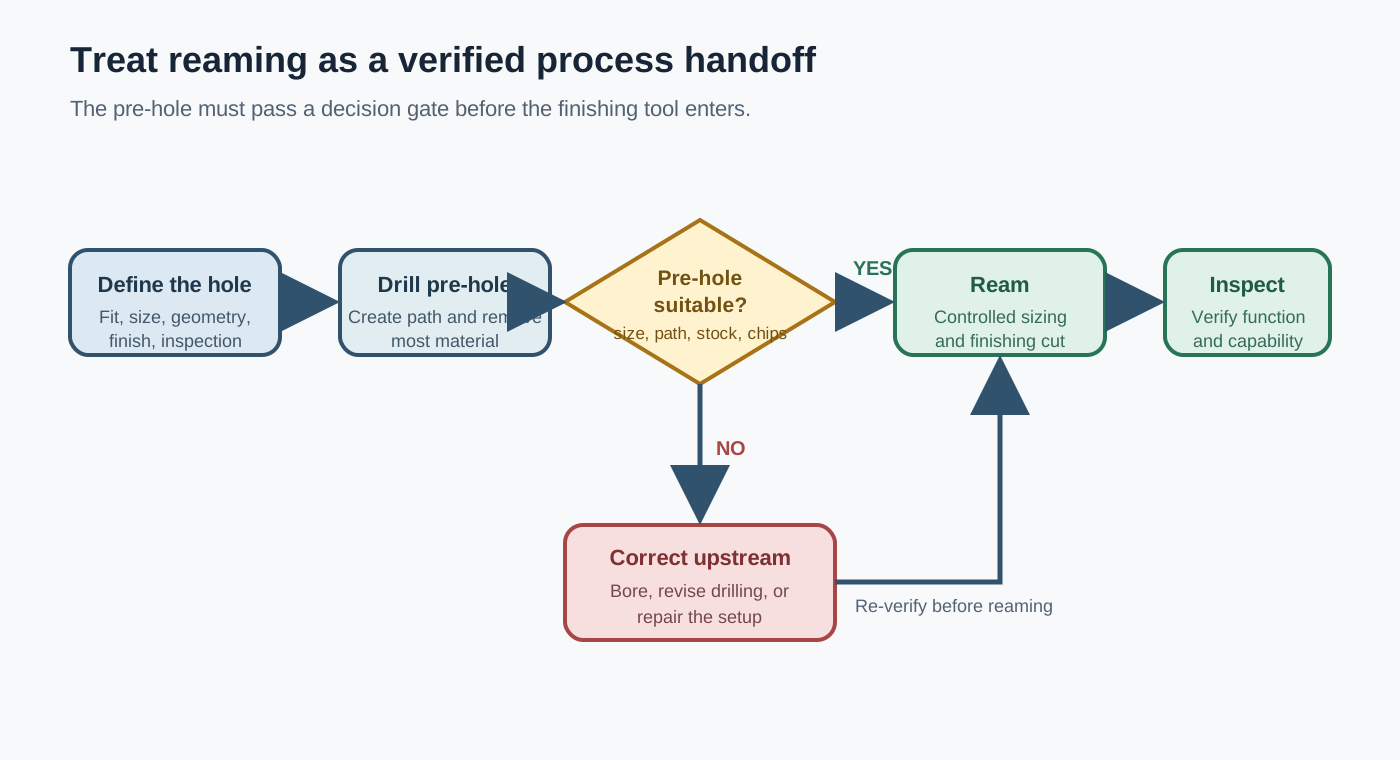
A practical process plan records:
- the final requirement and measurement method;
- the selected drill and expected pre-hole range;
- the stock allowance required by the chosen reamer under the actual conditions;
- the alignment and runout checks for the complete spindle-holder-tool assembly;
- the entry, feed, coolant, and chip-flow strategy;
- the reaming depth and safe withdrawal method;
- in-process and final inspection points;
- the response if the pre-hole is outside its release limits.
The release limit for the pre-hole should be tied to the finishing process. A pre-hole may be acceptable as a drilled feature yet unsuitable for reaming if it leaves the wrong stock distribution, insufficient bottom clearance, or a chip-control problem.
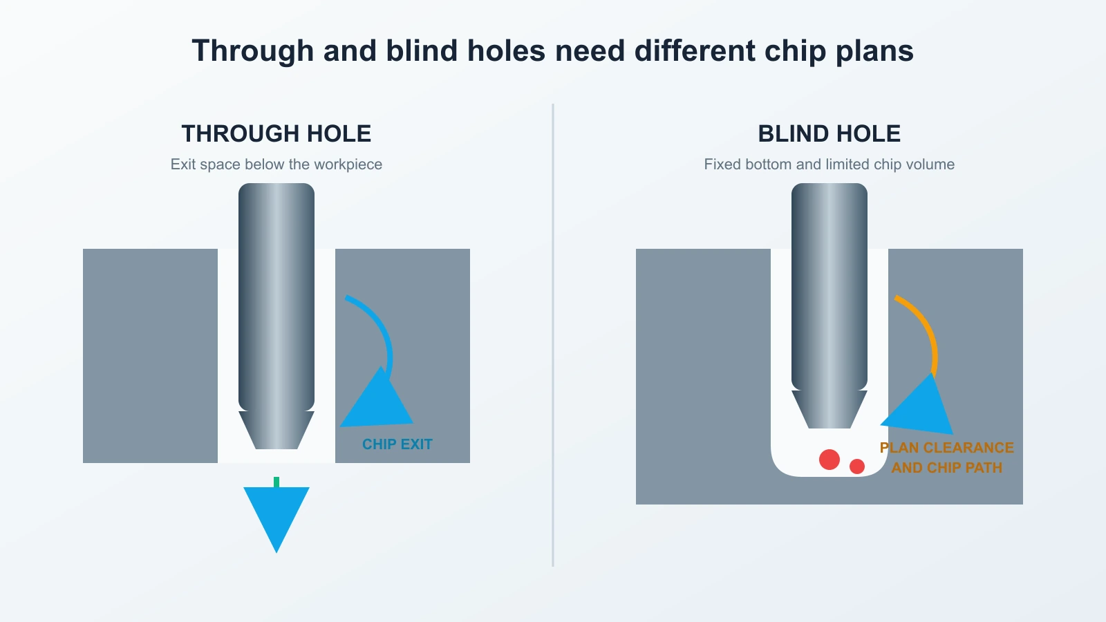
Through holes
Through holes offer an exit path, but the operation still needs room for the reamer lead and chips beyond the finished surface. Confirm that the tool can pass far enough to complete the cutting action without colliding with fixtures or sacrificial material. Plan for the breakthrough condition: interrupted support at exit can affect burr formation and cutting load.
Chip direction matters. The flute design, coolant path, material, and orientation should help move chips away from the finished surface rather than pull them back through the bore. If chips collect below the part or against a fixture, “through” does not necessarily mean free evacuation.
Blind holes
A blind hole introduces a fixed bottom and limited chip volume. Separate total drilled depth from usable finished depth. The drill point, reamer lead, bottom clearance, and any uncut region must fit below the specified functional length without contacting the bottom unexpectedly.
Determine where chips will go during the cut and withdrawal. Coolant must reach the cutting edges and support the intended evacuation path. Packing chips at the bottom can damage the surface, increase load, or prevent the reamer from reaching depth. The correct solution depends on reamer geometry and delivery method; do not assume a through-hole cycle can be copied unchanged.
Specify the finishing tool after defining the pre-hole
Do not select a reamer from final diameter alone. Before comparing candidate tools, record:
- workpiece material and condition;
- final diameter, tolerance, fit, and inspection method;
- required finished length and total hole depth;
- through, blind, or interrupted geometry;
- pre-hole diameter, geometry, and stock allowance;
- whether location or straightness has already been established;
- machine type, spindle condition, holder, and available runout control;
- coolant type, concentration, pressure, and delivery path where relevant;
- production volume and tool-change criteria;
- entry and withdrawal constraints.
The carbide reamer collection is a navigation point for identifying candidate tool families after those inputs are known. It is not a substitute for confirming the selected tool’s actual geometry, dimensions, application limits, and cutting data.
Tool selection should also reflect what happens at the lead and where chips must travel. Flute form, lead geometry, margin design, coolant delivery, and overall reach can change the process, but they must be verified from the chosen tool’s documentation. The PCD reamer range is another product-family reference after those inputs are defined; neither a PCD nor generic carbide label establishes suitability for a blind hole, interrupted cut, particular material, or target fit.
Diagnose the process at the correct stage
When a finished hole fails, preserve evidence from both stages. Measure the drilled pre-hole on a controlled sample before reaming, then compare it with the final result. Changing the drill, reamer, holder, allowance, speed, feed, and coolant at once makes it impossible to assign the cause.
- Location is wrong before and after reaming: Inspect spotting, drill wander, fixture relationship, spindle alignment, and the drilling toolpath. If location must be corrected, use a process capable of moving the hole path rather than asking the reamer to follow it differently.
- Final diameter is oversize or inconsistent: Check the measurement method first, then total indicated runout, holder cleanliness, reamer condition, alignment, pre-hole size and stock distribution, cutting load, and material behavior. Keep full oversize diagnosis on its dedicated troubleshooting page.
- Surface finish is poor: Compare the pre-hole surface with the reamed surface. Inspect cutting edges, actual allowance, chip recutting, coolant delivery, chatter, feed behavior, and withdrawal marks before assuming the tool family is wrong.
- The hole is tapered or bell-mouthed: Check entry alignment, tool guidance, fixture rigidity, pre-hole taper, runout, and whether cutting load changes with depth.
- The reamer rubs or wears rapidly: Verify that it is removing enough controlled material to cut, that the work material and tool are compatible, and that coolant reaches the active edges. Also check for contact outside the intended cutting region.
- The bottom or exit is damaged: Inspect chip accumulation, lead clearance, breakthrough support, usable depth, bottom contact, and the withdrawal path.
Use one-variable corrections after the likely stage has been identified. If the pre-hole is already outside the process window, stabilize drilling or add correction before tuning the reamer. If the pre-hole is stable and the failure appears only after finishing, focus on the reaming setup and cycle.
When the drill alone is enough
Reaming adds a tool, a cycle, inspection requirements, and another source of variation. It should close a demonstrated gap, not appear automatically on every controlled hole.
A drill-to-size route is defensible when capability evidence shows that the process meets the functional requirements at the required production rate. Evidence should cover more than the first part with a new tool. Sample across relevant cavities, hole depths, machines or spindles, tool life, material lots, and environmental conditions. Use a measurement system capable of resolving the tolerance and surface requirement being evaluated.
Also examine the consequence of failure. A clearance hole with a generous functional window may not justify a finishing step. A fit-critical locating feature may justify reaming, boring, honing, or another process even if some drilled holes fall inside the limits. The correct decision balances capability, repeatability, inspection cost, cycle time, and risk.
Do not treat solid carbide drills as a guarantee of the final result. Carbide can provide stiffness and wear advantages in suitable applications, but the complete process still includes tool geometry, machine and holder condition, entry, evacuation, material behavior, and measurement. Prove the route rather than relying on the tool label.
Conclusion: use reaming to close a verified capability gap
A drill creates the hole and removes most of its material. A reamer finishes a prepared existing hole when final size consistency or surface finish requires a controlled second cut. The pre-hole, stock allowance, alignment, chip path, and inspection method are all part of that finishing operation.
If the remaining gap is location, alignment, or major geometry, correct it before reaming. If drilling already meets the drawing and functional requirement repeatedly, stop at drilling. The best process is the shortest verified route that controls the errors the part actually cares about.