Skip to content
Indexable End Mill vs Solid Carbide: Choose by Process Economics
For indexable end mill vs solid carbide selection, start with the process envelope rather than looking for one winner. A solid carbide end mill is often attractive at smaller diameters, where compact geometry, high edge count, specialized flute forms, and finish capability matter. An indexable cutter often becomes attractive as diameter, roughing volume, and edge consumption increase, because worn edges can be indexed or replaced without discarding the body. The crossover still depends on the machine, feature, material, cycle, tool life, and cost per accepted part.
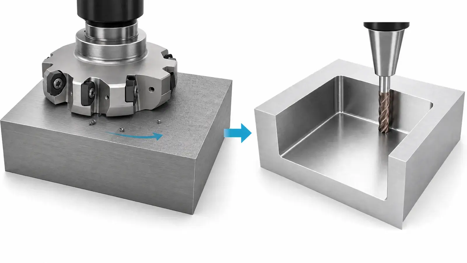
Many shops should use both. An indexable body can remove bulk stock, while a solid tool finishes corners, walls, or details the inserts cannot reach. The correct comparison is therefore not only tool against tool. It is one complete process route against another.
What changes when the cutting edge becomes replaceable
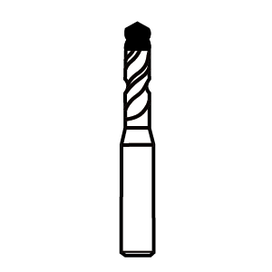
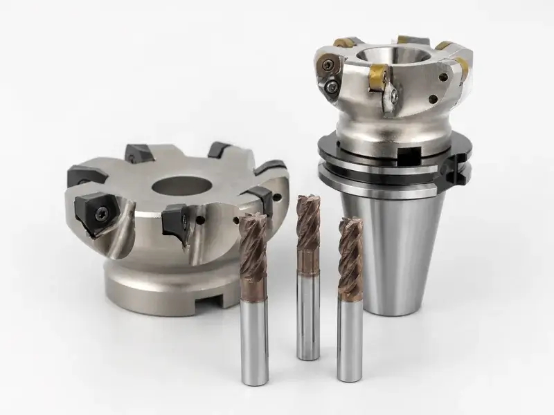
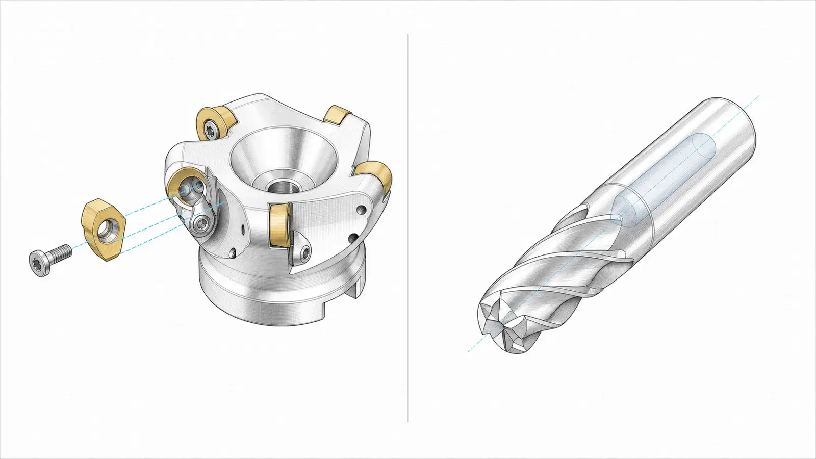
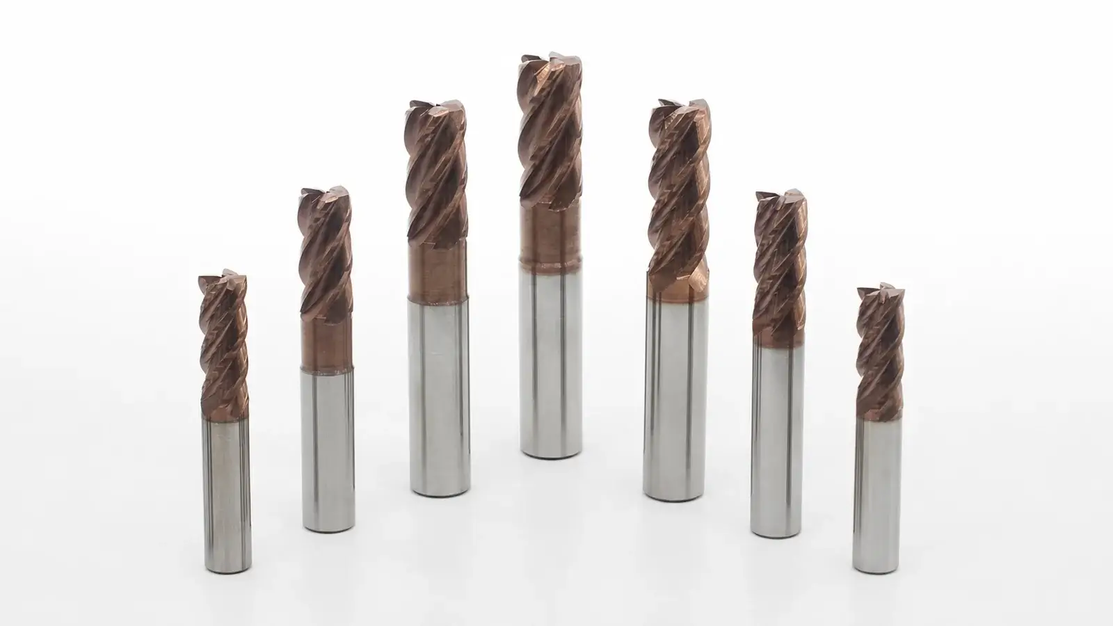
A solid carbide end mill is a monolithic cutter: the shank, core, flutes, and cutting edges belong to one tool. That construction supports small diameters and a wide range of flute counts, helix forms, corner geometries, chip breakers, necks, and finishing designs. When an edge is damaged or worn beyond the process limit, the cutter is replaced or sent for controlled reconditioning where appropriate.
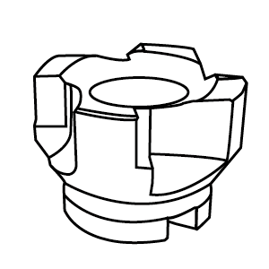
An indexable end mill separates the durable cutter body from replaceable inserts. The body locates the inserts, transfers force to the holder, and may accept different insert grades or geometries within its approved system. A worn edge can be indexed to another usable corner or the insert replaced. This changes both the economics and the maintenance burden.
The replaceable edge introduces interfaces that a monolithic cutter does not have: insert seats, screws, pockets, edge orientation, body condition, and insert-to-insert height variation. A damaged seat or trapped chip can affect runout and load sharing even when the new insert itself is correct. Conversely, a chipped solid tool may require replacement of the complete cutter rather than one edge.
The broad construction difference is well summarized by comparing solid-carbide and indexable milling tools. Application observations remain starting points; the selected body, insert, solid tool, and machine data still control the operation.
Start with diameter, reach, and required geometry
Diameter changes the practical and economic comparison. At a small envelope, there may not be enough room for a replaceable insert, screw, seat, and strong body. Solid carbide can package cutting geometry into a smaller diameter. As diameter grows, the material cost of a large monolithic carbide tool rises, while a reusable steel or carbide body with replaceable inserts may spread ownership cost across many edge changes.
There is no universal crossover diameter. Tool design, insert size, number of teeth, body material, application, local pricing, and available product families change it. Obtain real quotations for candidate tools rather than relying on a remembered threshold.
Reach can also reverse the expected choice. A long, small solid tool may deflect or become prohibitively expensive; an indexable body may offer a relieved shank or modular extension. In another feature, insert geometry or body clearance may prevent the indexable cutter from reaching a narrow corner that a necked solid tool can finish.
Check the feature before the platform:
- minimum internal radius and floor corner;
- axial cutting length and total reach;
- wall, floor, and contour geometry;
- ramping, helical entry, plunging, slotting, or profiling requirements;
- holder and spindle-nose clearance;
- required finish and size control;
- whether one body or insert leaves uncut stock that needs a second tool.
The platform that fits the nominal diameter may still fail the geometry contract.
Separate roughing from finishing
Roughing rewards reliable material removal rate, edge economy, chip control, and tolerance to interrupted or variable stock. Finishing rewards predictable runout, low deflection, accessible geometry, and stable surface generation. One cutter can sometimes do both, but combining the roles should be justified by accepted-part output rather than by avoiding a tool change.
An indexable shoulder mill or high-feed body may remove large stock efficiently when the machine can provide the required power, feed, and rigidity. Replaceable inserts can reduce the financial impact of edge consumption, and grades can be changed for different materials within the body’s approved system. But insert radius, lead angle, body diameter, and tooth runout can leave stock or finish conditions that require another pass.
A solid carbide tool can be effective for high-speed, lower-engagement roughing and can reach smaller corners with more flute and geometry options. It may also finish with the same tool after roughing. Yet a long cycle with many light passes is not automatically economical simply because the tool survives.
A human-reviewed shop discussion about indexable versus solid tools for profile roughing captures the real question: cycle time saved by a different roughing strategy must be weighed against machine capability, insert behavior, finish allowance, and the remaining operations. The case is experience evidence whose material removal rate remains tied to its setup.
A common route is indexable roughing followed by solid-carbide semi-finishing or finishing. Another job may use solid carbide throughout because diameter, access, spindle speed, and geometry favor it. A third may rough and finish with indexable inserts when the body, wiper geometry, runout, and surface requirement support that choice.
Let the machine expose the real limit
Tool capability is useful only inside the machine’s operating envelope. A small solid carbide cutter may need spindle speed the machine cannot reach. A larger indexable body may demand torque, power, feed, or rigidity the machine cannot supply. The setup may chatter before either catalog’s nominal productivity is available.
Record:
- usable spindle-speed range under load;
- continuous and short-term power or torque limits;
- maximum controllable feed and acceleration;
- spindle, holder, and tool runout;
- tool overhang and fixture rigidity;
- radial and axial engagement;
- coolant or air delivery and chip capacity;
- workpiece stability as stock is removed.
Do not describe one platform as “more rigid” without specifying diameter, body/core geometry, stickout, holder, insert shape, engagement, and setup. A monolithic carbide tool has no insert joint, but a larger indexable body may be much stiffer than a smaller long-reach solid cutter. An unstable part can make the lower-force option more productive even when its theoretical removal rate is lower.
The shop experience comparing indexable high-feed and solid-carbide roughing illustrates how part geometry, machine, reach, and toolpath determine whether a nominally aggressive tool can use its advantage.
Calculate cost per accepted part
Purchase price alone produces poor decisions. An insert may look inexpensive until body cost, unused corners, indexing labor, seat damage, and stockouts are counted. A solid tool may look expensive until its cycle time, finish, reconditioning, or elimination of a second tool is included.
Use the same accounting window for both routes.
| Cost input | Indexable route: measure | Solid-carbide route: measure | Evidence source |
|---|---|---|---|
| Tool ownership | Body price and accepted body life, spread across production | New cutter price minus verified reconditioning value | Purchase and tool-room records |
| Usable cutting edges | Inserts consumed, usable corners, abnormal edge loss | Cutters consumed and usable life before change | Edge/cutter change log |
| Change labor | Indexing, seat cleaning, screw checks, offset verification | Tool replacement, presetting, offset verification | Observed labor time |
| Cycle output | Cycle time and accepted parts per edge | Cycle time and accepted parts per cutter | Machine and production data |
| Supply continuity | Insert grade/geometry availability and body-system continuity | Cutter availability and regrind/new-tool lead time | Approved supplier and inventory records |
| Quality risk | Scrap, rework, size drift, finish failures, seat/body incidents | Scrap, rework, wear drift, breakage, regrind variation | Quality records |
Calculate cost per part using accepted output, not pieces started. Include machining time at the shop’s burdened rate, tool and insert consumption, change labor, inspection, rework, and scrap. If one route adds a finishing tool or removes an operation, include that difference too.
Material removal rate belongs in the model, but it is not the model. A higher material removal rate that overloads the machine, damages inserts unpredictably, or creates more finish work may raise total cost per part. A slower route may also lose if long cycle time dominates every other saving.
Track cost per part across enough production to include normal wear and variation. One new body with fresh inserts and one fresh solid cutter do not establish a stable crossover.
Count the failure modes introduced by each platform
For an indexable cutter, inspect insert seats, screws, pocket damage, edge orientation, insert grade and geometry, chip entrapment, body runout, and load sharing. Replacing an insert without correcting a damaged or dirty seat can repeat the failure. Mixing edge conditions or incorrect inserts can make one tooth carry disproportionate load.
For a solid carbide end mill, inspect flute wear, corner damage, chipped edges, coating condition, shank and holder contact, runout, pullout, and any regrind change to diameter or geometry. A surviving tool is not necessarily producing an acceptable process if size or finish has drifted.
Both platforms can fail from the same upstream causes: excessive stickout, poor holder condition, unstable workholding, wrong engagement, recut chips, unsuitable cutting data, or a machine operating outside its stable zone. Diagnose the complete system before blaming the platform.
Define the inputs before choosing a platform
Specify the work material, operation, stock condition, diameter, reach, corner geometry, engagement, roughing and finishing allowances, target cycle, quality requirements, machine limits, holder, coolant, volume, and approved suppliers.
Use the indexable cutting tools page to identify candidate families after those inputs are defined. Confirm the actual body, insert interface, grades, dimensions, availability, and application data; a category page does not establish fitness for a particular operation.
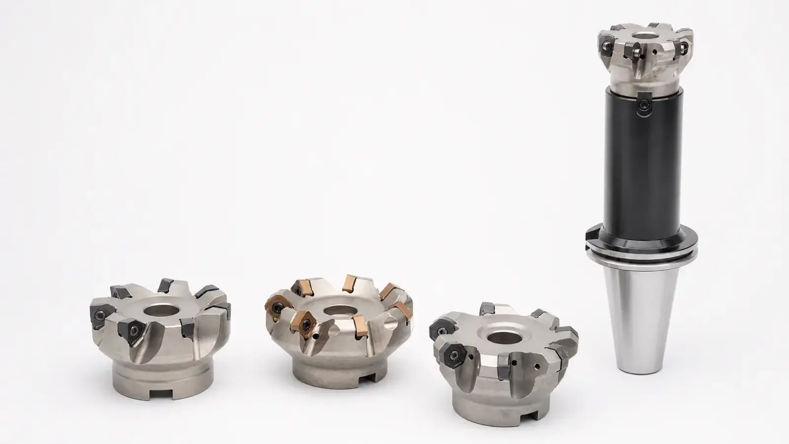
For each candidate, document the body and insert combination or the exact solid tool. A body without a sustainable insert supply is not a durable platform. A solid tool whose geometry cannot be replaced consistently is also an inventory risk.
Release the choice with an A/B production trial
Run equivalent, controlled trials when the economic crossover matters. Keep material, part revision, machine, workholding, stock condition, and inspection method comparable. Use cutting data appropriate to each candidate rather than forcing identical commands onto different geometries.
Record cycle time, material removal rate, spindle load, edge or cutter life, change labor, surface finish, dimensional behavior, rework, scrap, and operator interventions. Inspect the body or solid tool after the trial, not only the part.
Release the route that produces the required accepted output at the lowest sustainable cost per part. The result may be indexable, solid carbide, or a two-tool combination. If the decision cannot survive a change in insert price, body life, cutter life, machine availability, or scrap rate, record that sensitivity instead of presenting the crossover as permanent.