


Left-Hand Spiral, Right-Hand Cut End Mills: When to Use Them
For conventional metal-milling end mills, right-hand cutting with a right-hand spiral is the usual starting point. Consider a left-hand spiral, right-hand cut end mill when upward action is lifting a supported thin part or damaging its top edge—and chips have room to escape toward the tip. It changes the axial cutting action without requiring left-hand cutting.
Choose the cutting hand first, then the spiral. A tool that cuts in the correct direction can still lift the wrong surface or push chips into a closed space. The useful question is not simply “left or right?” but which combination suits the workpiece, support and chip exit.
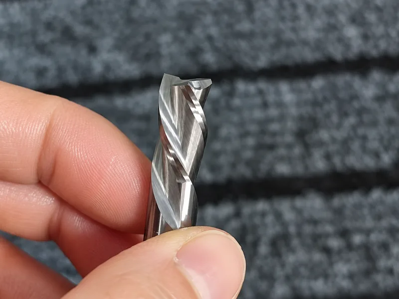
Start with the cutting direction, not the flute spiral
Cutting hand describes the direction the cutting edges are designed to work in; rotation is the actual motion of the spindle. They must match. Right-hand cutting is the usual choice for conventional end milling. Left-hand cutting is a separate requirement for setups such as mirror-image arrangements—not the normal way to obtain downcut action.
Always state the viewing direction when using clockwise or counterclockwise. Viewed from the tip toward the shank, a right-hand-cut end mill rotates counterclockwise. Looking from the opposite end reverses the apparent direction:
| Cutting hand | Viewed from tip toward shank | Viewed from shank toward tip |
|---|---|---|
| Right-hand cut | Counterclockwise (CCW) | Clockwise (CW) |
| Left-hand cut | Clockwise (CW) | Counterclockwise (CCW) |
These are two views of the same physical rotation. Reversing the spindle does not turn a right-hand-cut end mill into a left-hand-cut end mill: its rake and clearance are designed for the intended direction. Check the tool specification, not a mirrored photograph or an unlabelled rotation arrow.
Upcut vs downcut: choose the spiral within that cutting hand
Spiral hand, also called helix hand, is the geometric handedness of the flutes, like a screw thread. It is not a spindle rotation instruction. With right-hand cutting already selected, a right-hand spiral tends to carry chips toward the shank; a left-hand spiral tends to carry them toward the tip.
The four combinations below apply to conventional single-helix end mills running in their designed cutting direction. “Up” assumes the shank is above the tip; shank and tip remain the clearer references on a horizontal spindle.
| First: cutting hand | Rotation viewed from tip toward shank | Then: spiral hand | Axial chip-transport tendency |
|---|---|---|---|
| Right-hand cut | Counterclockwise (CCW) | Right-hand spiral | Upcut — toward the shank |
| Right-hand cut | Counterclockwise (CCW) | Left-hand spiral | Downcut — toward the tip |
| Left-hand cut | Clockwise (CW) | Left-hand spiral | Upcut — toward the shank |
| Left-hand cut | Clockwise (CW) | Right-hand spiral | Downcut — toward the tip |
Matching cutting and spiral hands give upcut; opposite hands give downcut. A left-hand spiral is therefore not always downcut. Actual chip movement also depends on material, engagement, flute space, coolant and extraction; the table is not a guarantee that every chip follows the helix.
Upcut/downcut also does not mean climb/conventional milling. Those describe cutter motion relative to workpiece feed at engagement. Changing that feed relationship does not change the tool's cutting hand or spiral.
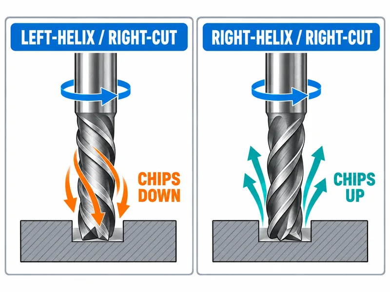
Decide which surface needs support
An upcut action can pull on a thin or lightly restrained workpiece. In a layered material, that load can also act on the surface layers rather than moving the whole part as one rigid body. Workholding and the laminate structure therefore matter alongside the tool geometry.
A downcut tool can be useful when its axial action presses the workpiece into a supporting surface. But the support must actually be there. A sheet spanning a gap can still deflect under a downward load, and pressing on one face does not guarantee a clean edge on the opposite face.
Begin with the defect: is the top edge fraying, the lower face breaking out, or the entire part lifting? Then identify which surface is supported and which section of the cutting edge is engaged. A change of helix should address that specific problem.
This reasoning is not limited to composites. Thin metal parts can also be sensitive to lifting forces. Nor does every composite require a downcut cutter. The part's support, edge requirement and chip path decide whether the change is useful.
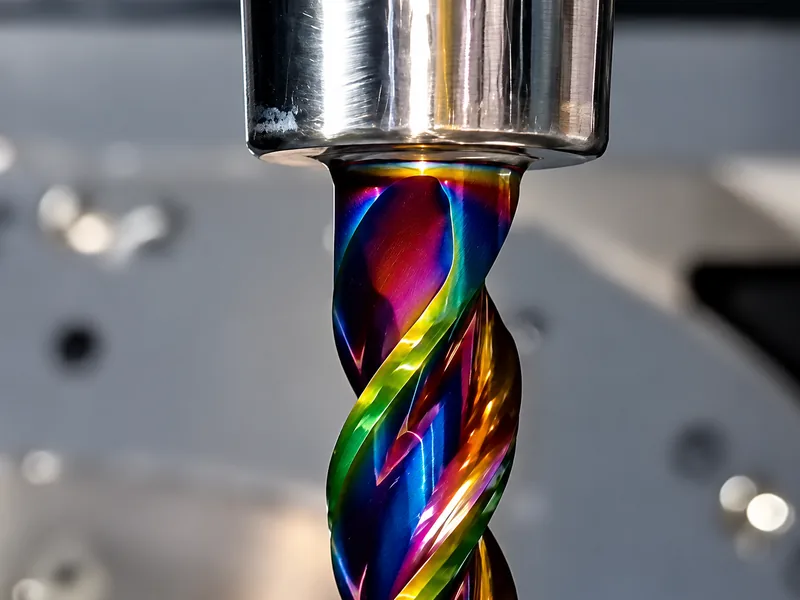
A downcut needs somewhere to send the chips
At an open external profile, chips pushed toward the lower edge may have an escape route. Inside a blind pocket or deep closed slot, the same tendency can carry chips into a confined space. Chip recutting and packing then become part of the process assessment.
Do not judge the result solely by a cleaner top edge. Inspect evacuation, the lower edge, tool loading and signs of damage through the complete cut. A setup that improves one surface while trapping chips has exchanged one problem for another.
Before replacing an upcut tool, compare the full engagement: side profiling, slotting and axial entry do not expose the same parts of the tool or provide the same evacuation path. Some purpose-designed downcut tools permit plunging, while others do not. Downcut alone is neither permission nor a blanket ban: confirm the exact cutter's centre-cutting capability, permitted entry method and evacuation requirements.
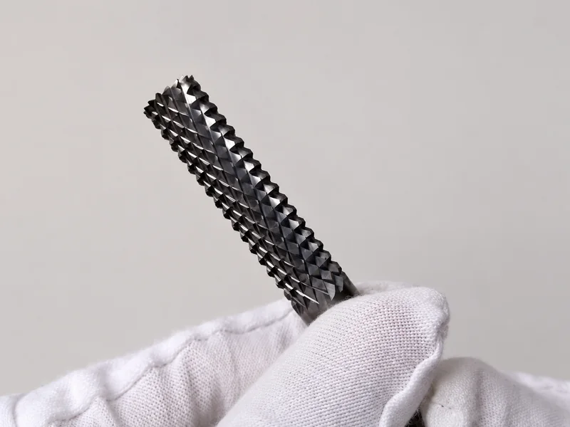
When intersecting teeth help with composite side milling
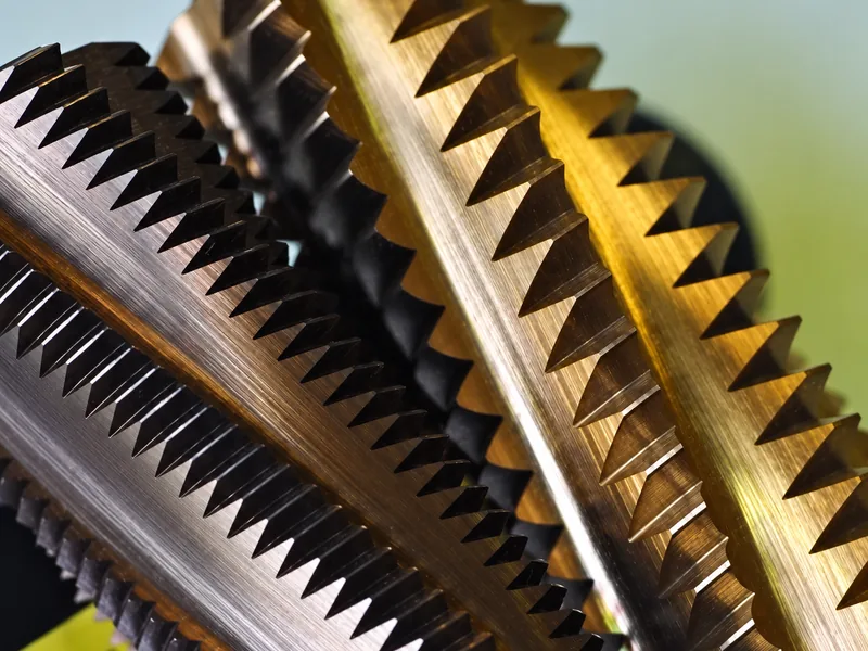
For roughing or profiling fibre-rich composites, a cutter with intersecting left- and right-hand teeth can divide the cutting action and shear fibres into smaller pieces. This gives a specific reason to consider a cross-cut or diamond-cut geometry when fibre separation and chip breakup are the main difficulty in the side cut.
Judge the resulting edge as well as material removal. A geometry that breaks fibres effectively may still leave a surface requiring a finishing pass. Choose it for the work it must do, rather than assuming that more teeth necessarily produce a smoother wall.
The overall axial tendency depends on the actual design. Intersecting teeth do not by themselves prove balanced forces. Keep the laminate supported and check fraying or damage at both faces. “Diamond-cut” can describe the tooth pattern; the name alone does not identify PCD as the cutting material.
Use a compression cutter when both laminate faces need control
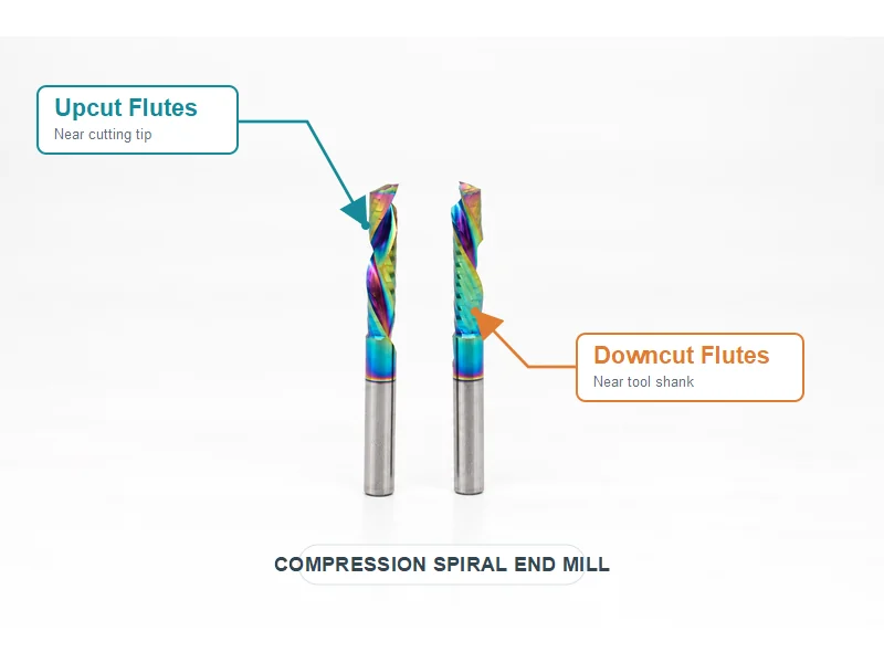
A compression cutter has an upcut section near the tip and a downcut section nearer the shank. With the transition inside the sheet, the two sections act toward the laminate interior. That is a different arrangement from teeth crossing over the same cutting length.
Match the upcut length and transition position to the sheet thickness and engaged depth. If a shallow pass uses only the upcut section, the intended two-face compression action is not present. Check the tool's geometry against the actual toolpath before choosing it for edge quality.
Inspect both faces, the sidewall and chip evacuation in the trial. A cleaner top edge alone does not establish that the whole feature improved.
Do drills, reamers and straight-flute tools follow the same rule?
Can the same selection rule be used for drills and reamers?
Right-hand spiral with right-hand cutting is common in conventional end mills and twist drills, with chips generally travelling toward the shank. But the practical choice cannot be extended to all metal-cutting tools. Reamers also commonly use straight flutes or left-hand spiral with right-hand cutting. A left-hand-spiral, right-hand-cut reamer can push chips ahead and is a useful option for through holes. Hole type, material, interruptions and the particular reamer design govern the choice; an end-mill default is not a reamer rule.
What about straight flutes and through-tool coolant?
A straight flute has no left- or right-hand helix, but the tool still has a cutting hand. It lacks the axial chip-transport contribution of a helix; that does not mean coolant alone decides where chips go. Cutting-lead geometry, chip shape, flute space, hole type, feed and the coolant return path all matter.
Coolant emerging near the tip does not prove chips must leave toward the tip. In a blind hole, fluid can return along the flutes toward the hole mouth and carry chips with it. Check that return path, not just the outlet position.
Sundi straight-flute drilling demonstration. A straight flute has no helix hand; assess chip evacuation for the actual hole, geometry and coolant return path.
Specify both directions when ordering a replacement
A useful specification includes the cutting hand and spiral hand separately, plus diameter, usable cutting length, shank, workpiece material and operation. For sheet work, add thickness, support arrangement and which face or edge must remain clean. For a mixed-helix tool, include a drawing showing the sections.
If a replacement rotates correctly but produces different burrs, lifting or evacuation, compare these details before changing cutting parameters. The mismatch may be structural: the new tool can be a valid right-hand-cut cutter and still be wrong for the established process.
Helix angle is another variable; it is not the same as helix hand. The separate guide to end-mill helix angle covers that distinction in more detail. For a replacement, specify both hands explicitly: first the cutting direction the setup requires, then the spiral that provides the intended axial action and chip path.
For an application review, see our carbide milling cutters and compression router bits. Send the tool or workpiece drawing, material, cutting direction and support arrangement so our team can discuss the required geometry.