



Milling Chatter: Diagnose the Cause Before You Change the Cut
Milling chatter is not a single bad setting. It is an unstable interaction among the machine, spindle, holder, cutter, workpiece, fixture and cutting conditions. Changing three parameters at once may make the noise disappear, but it does not show which part of that system was responsible—or whether the next feature will chatter again.
If vibration is escalating, the tool is visibly damaged, the workpiece or fixture is moving, or spindle load is approaching an unsafe level, stop the cut under the shop’s approved procedure. Otherwise, preserve the evidence. Record the exact condition that produced the symptom, inspect the mechanical chain, choose one plausible cause, and run a test that can disprove it. Only then should feeds, speeds or engagement be changed.
Confirm that the pattern is cutting-induced chatter
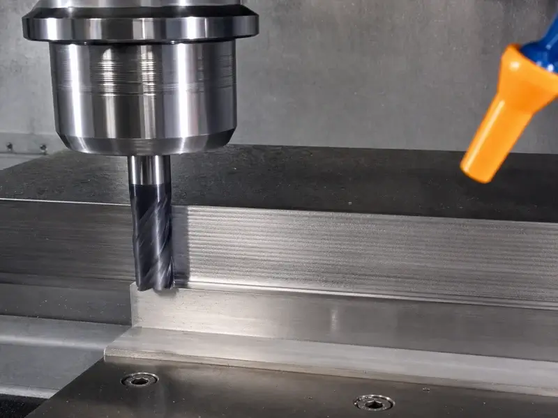
Chatter usually announces itself through more than sound. A repeating wave or faceted pattern appears on the machined surface. The pitch or angle of the marks may change with spindle speed, flute count or direction. Cutting sound becomes tonal or pulses as the tool moves through a specific feature. Load may oscillate rather than simply increase. A fresh edge may show uneven wear because one flute is carrying more work than the others.
The mechanism is often regenerative. A tooth deflects the tool-workpiece system and leaves a wavy surface. The next tooth meets a chip whose thickness now varies with that waviness. Cutting force varies in response, adding energy to a flexible structural mode. Under the wrong combination of stiffness, damping, engagement and tooth-passing timing, the vibration sustains or grows.
Not every vibration is regenerative chatter. An out-of-balance holder or tool can vibrate in air. A damaged bearing, loose head, contaminated taper or poorly seated holder can produce noise before the edge engages. Chip recutting can score a wall irregularly. A chipped flute can leave a once-per-revolution mark. An interrupted cut naturally produces impacts. A workpiece that shifts is a workholding failure, not a stability-window problem.
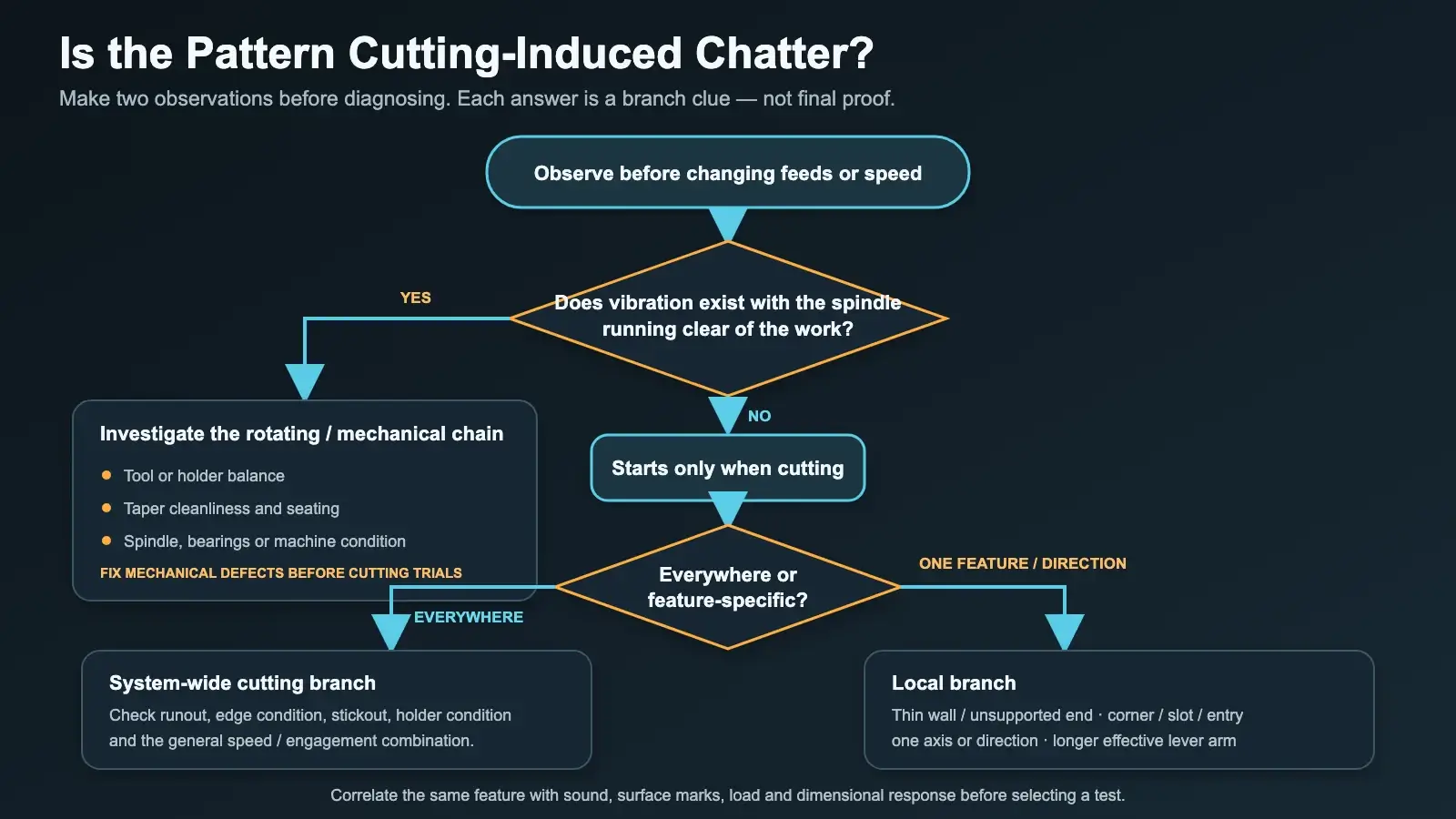
Make two observations before diagnosing:
- Does the vibration exist with the spindle running clear of the work, or begin only as the edge engages?
- Does it occur everywhere, or only at one depth, corner, wall, direction or unsupported region?
Vibration in air sends the investigation toward spindle, holder, tool balance, seating or machine condition. A symptom tied to one feature sends it toward local support, engagement or toolpath. A symptom that appears only after the cutter reaches a longer effective lever arm implicates stiffness. These are branch clues, not final proof.
Read the surface finish as a time record. Evenly spaced waves that continue through a constant-engagement region support a periodic interaction; a mark that appears only where direction reverses may point to backlash, dwell or path behavior instead. A single deep line may be a trapped chip or damaged edge rather than chatter. Compare mark direction with tool travel and inspect whether the wavelength changes after a controlled RPM trial. Do not infer a precise vibration frequency from visual spacing unless feed, path and measurement method are known, but use the pattern to decide which evidence to collect next.
Sound should be treated the same way. A high tonal sound can accompany chatter, yet a quiet low-frequency structural motion can still damage size and finish. Conversely, some interrupted operations are loud while remaining controlled. The diagnostic target is repeatable correlation among engagement, sound, marks, load and dimensional response—not a subjective threshold for what “bad” sounds like.
Freeze the evidence before changing the cut
An undocumented “bad cut” cannot be compared with the next trial. Save the program revision and record:
- machine and spindle;
- tool manufacturer, item number, diameter, flute count and edge condition;
- holder, collet or interface, assembly length and measured tool stickout;
- indicated runout and where it was measured;
- work material, condition and feature location;
- fixture contact points, clamp locations and unsupported span;
- spindle speed, feed per tooth or programmed feed, and actual overrides;
- radial engagement, axial engagement, entry, exit and cutting direction;
- coolant or air delivery and observed chip evacuation;
- the moment chatter begins, its sound, visible mark direction and load behavior.
Photograph the setup and surface if shop policy allows. Mark the exact region on the program or inspection record. If the next trial changes both tool stickout and spindle speed, the result cannot tell you which change mattered. Return to the baseline whenever a test is inconclusive.
Do not assume that a smaller number means a gentler, more stable cut. Very low chip load can make the edge rub instead of shear cleanly. A shallow axial cut can move engagement onto a less favorable portion of the flute or structure. A tiny change in spindle speed may leave tooth-passing excitation near the same structural response. The baseline record prevents this kind of guess from becoming shop folklore.
Inspect the force path from spindle to workpiece
Before editing the program, follow the cutting force through the physical system: machine structure, spindle and taper, holder, cutter, workpiece, fixture and table. Every interface should be clean, seated, clamped and supported as intended.
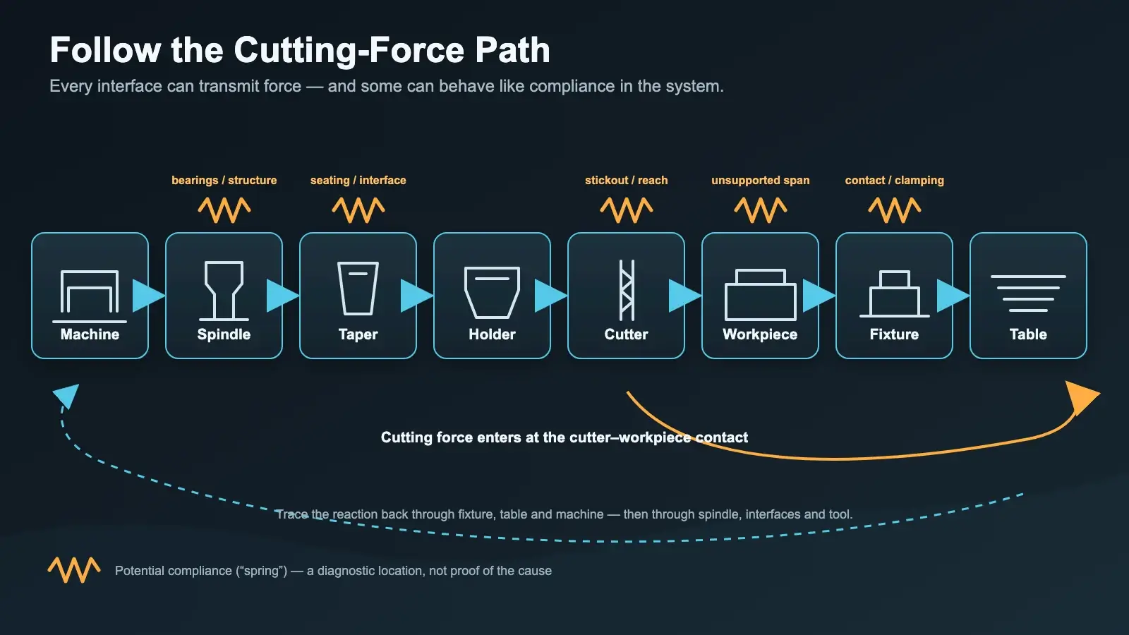
With the machine in a safe inspection state, check for contamination or damage at the spindle taper and holder interface. Confirm the retention or drawbar condition according to machine procedures. Inspect the holder, nut, collet and cutter shank for fretting, dirt, burrs or improper seating. Do not compensate for a damaged interface by overtightening it beyond the manufacturer’s procedure.
Look for evidence of machine looseness: a head or ram that can shift under the cut, excessive axis play, a loose gib, abnormal spindle play, deteriorated bearings, or a table/fixture interface that is not fully seated. These checks are machine-specific and may require maintenance personnel. Chatter advice must not become authorization to adjust spindle bearings or machine geometry without the correct procedure.
At the workpiece, identify the shortest route from the cutting zone into a rigid support. Clamps can apply high force and still leave a long flexible span. A thin wall may deflect between support points. A vise jaw may hold the stock while the machined feature projects far above it. Repositioning support near the force, changing force direction or altering the cutting sequence can be more effective than simply adding clamp torque.
The direction of force matters. A setup may be stable when the cutter pulls the work toward a supported face and unstable in the reverse direction. On machines with backlash or less rigid architecture, climb and conventional motion can interact differently with the mechanism. Do not prescribe one direction universally; compare the actual force path, machine condition and approved operating practice.
Check the tool, holder and effective reach
Measure runout rather than judging it by eye. Check at a location appropriate to the holder and cutter, record that location, and rotate the assembly through a complete revolution. If runout is excessive, isolate whether it follows the cutter, collet, holder or spindle interface by cleaning and reseating components under the approved process or substituting a known-good component.
Runout changes load sharing. One flute may remove most of the chip while another rubs. The programmed average feed per tooth can therefore hide a much higher effective load on the leading edge. Uneven flute wear, once-per-revolution marks and a symptom that follows the assembly are evidence for this branch.
Inspect edges for chipping, built-up material and uneven wear. Confirm that the cutter geometry and cutting length match the operation. Minimize tool stickout while preserving required clearance; stiffness falls rapidly as a slender cutter extends farther from its support. Also minimize unnecessary holder projection. If extra reach is essential, the stable engagement and path may differ from a short assembly.
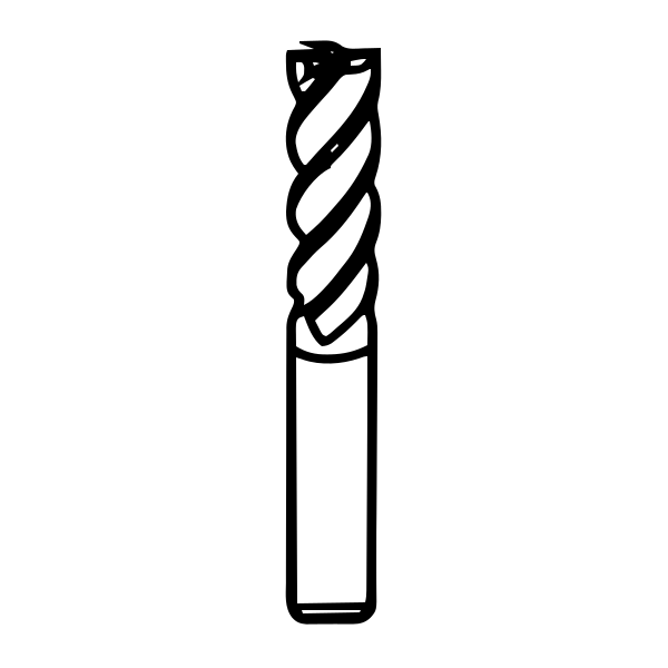
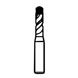
The solid carbide end mills can be used to identify candidate tool families and dimensions. It does not replace the selected tool’s drawing and application data, and this article does not claim that a particular geometry will cure chatter in every machine or material.
Flute count, helix, pitch, core and edge preparation affect cutting forces and excitation, but they cannot be separated from chip space, material, radial engagement and holder stiffness. A higher flute count changes tooth-passing frequency and available chip space; it is not automatically more stable. A variable-pitch or variable-helix design may disturb periodic excitation in an appropriate application, but it cannot repair a loose holder or unsupported workpiece.
Decide whether the workpiece or fixture is the spring
If chatter appears near the free end of a wall, at the end of a long plate, or after material removal has reduced section thickness, suspect the workpiece-fixture branch. Compare the same toolpath at locations with different support. A clear location dependency is stronger evidence than a general impression that the fixture “feels tight.”
Under safe static conditions, observe whether modest hand force or a permitted indicator test reveals movement at the cutting region. A tap or response comparison can help locate a flexible panel, but it is qualitative and must not replace dimensional or engineering checks where safety matters. Confirm actual contact under supports and parallels. A clamp can bow a thin part away from a support, creating a spring despite high clamping force.
Possible corrections include moving support closer to the feature, shortening the unsupported span, changing the machining sequence so more stock remains during the unstable cut, reducing force through engagement changes, or approaching from a direction that loads the part into support. Apply one change and repeat the same feature. If the symptom moves when support moves, the result identifies the branch.
Improved workholding does not prove the fixture was the only cause. Reviewed shop cases show symptoms persisting after a more rigid setup because tool reach, holder condition, engagement or machine response remained. Treat every unsuccessful correction as information: restore the baseline, update the hypothesis, and test the next branch.
Read the toolpath for engagement spikes
Plot where the chatter starts against cutter engagement. Full-width slotting, tight internal corners, abrupt entry, a large wrap angle, simultaneous contact on opposing surfaces, and a sudden increase in axial or radial engagement can raise cutting force and reduce chip escape. A finish pass can still chatter if the tool rubs, re-enters a wavy surface or contacts more geometry than the programmer intended.
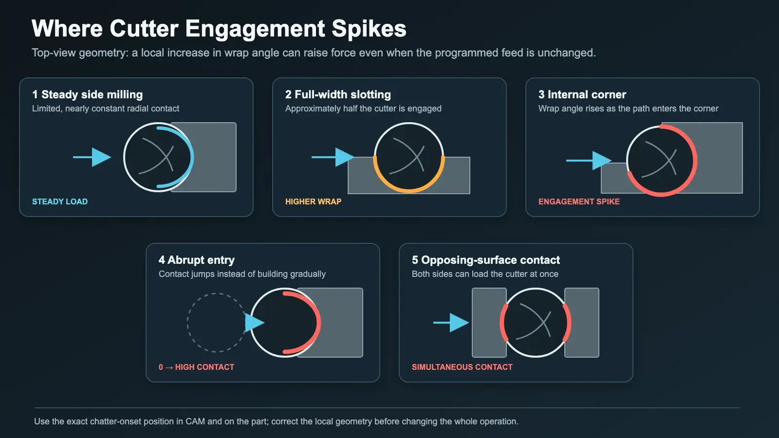
Check the CAM simulation and the physical feature together. Does the cutter enter at full engagement? Does radial contact increase in a corner? Is a ball or form tool cutting at an effective diameter different from the nominal diameter? Are both sides of a profile tool engaged? Does the exit leave a dwell or spring pass over an already unstable surface? Do chips collect in a pocket and re-enter the cut?
If the symptom occurs only at an engagement spike, correct the path before changing the whole operation. A controlled response might smooth the entry, reduce radial engagement locally, leave a planned roughing allowance, separate roughing and finishing, avoid simultaneous opposing contact, improve evacuation, or use a path that maintains a steadier load. Keep the selected cutting data tied to the actual toolmaker conditions and requalify after the geometry changes.
Do not reduce both axial and radial engagement automatically. That may lower force, but it also changes which part of the flute cuts, cycle time, chip thickness and structural excitation. Choose the engagement variable most directly connected to the observed spike and predict the response before testing it.
Change spindle speed as a frequency test
Once unsafe looseness, seating, runout, tool damage and obvious support problems are addressed, spindle speed becomes a diagnostic lever. It changes tooth-passing timing relative to the flexible system. The purpose is not to “go slower” by habit; it is to move the excitation away from an unstable interaction while staying within tool, material, machine and process limits.
Make a meaningful, documented change allowed by the selected tool data and machine. If spindle speed changes and feed per tooth is not the variable under test, recalculate table feed so chip load remains approximately constant:
table feed = RPM × effective flute count × feed per tooth
Otherwise, the trial changes both excitation frequency and chip load, and the result cannot distinguish them. Verify the effective flute count and do not reuse a linear feed calculated for the old RPM.
Compare the same feature. If the chatter band shifts, weakens or disappears predictably while other conditions remain fixed, speed interaction is supported. If nothing changes, return to baseline and investigate another branch or make a different controlled speed test within approved limits. One successful RPM is not a universal stable-speed recommendation; stability depends on this assembly, reach, engagement, material and structure.
When modal testing or verified stability-lobe data is available, use the responsible engineering or supplier method. This evidence package does not contain machine-specific modal data, so no stable-speed chart is supplied here.
Test chip load, engagement or path one variable at a time
Chip load is a separate hypothesis. Evidence of rubbing can include polished or smeared surfaces, heat without proportional material removal, squeal at very light engagement, built-up edge and deterioration during repeated spring passes. Evidence of overload can include rising spindle load, edge damage, excessive deflection, heavy burrs or loss of size. Neither diagnosis can be made from sound alone.
If rubbing is plausible and hardware checks pass, test a controlled feed-per-tooth change within the exact tool’s application data while holding spindle speed and engagement fixed. Predict that a cleaner chip and reduced rubbing signature should follow. If overload is plausible, reduce the directly implicated load variable under the same discipline and inspect the edge and surface response.
If engagement is the hypothesis, hold RPM and chip load constant while changing the relevant radial or axial contact or revising the local path. If tool reach is the hypothesis, use a shorter approved assembly while holding cutting conditions and feature geometry as close as practical. If chip evacuation is the hypothesis, correct delivery or exit path without simultaneously changing the cutter and speed.
Stop stacking changes. A shorter tool, lower RPM, different feed, lighter stepover and new holder may produce a quiet cut, but the shop cannot reproduce the reasoning when only one of those variables changes later.
Use the symptom-to-test matrix only after inspection
| Symptom pattern | Likely branch | Discriminating test | First controlled response |
|---|---|---|---|
| Vibration or tonal noise exists before cutting | Spindle, holder, tool balance, seating or machine condition | Run clear only under approved procedure; inspect and reseat or substitute known-good components | Correct the mechanical condition before cutting trials |
| Once-per-revolution marks and uneven flute wear | Runout, damaged edge or poor load sharing | Measure runout at a recorded location; inspect every flute | Clean/reseat or replace the identified component, then repeat baseline |
| Chatter occurs only near a thin wall or unsupported end | Workpiece or fixture flexibility | Compare supported and unsupported locations; change one support point | Shorten the force path or revise sequence/direction |
| Chatter begins in corners, slots, entry or simultaneous contact | Engagement or toolpath spike | Correlate CAM engagement with the exact onset position | Smooth or reduce the implicated local engagement while preserving other variables |
| Chatter changes strongly with a controlled RPM trial | Tooth-passing and structural interaction | Change spindle speed within limits and recalculate feed to preserve chip load | Qualify the stable condition for this exact assembly and engagement |
The matrix is a routing aid, not a substitute for inspection. Several branches can coexist. Excessive runout may make a long tool more sensitive to a corner; a flexible wall may amplify a speed-dependent instability. Resolve safety and mechanical defects first, then isolate the remaining cutting interaction.
Prove the correction on the same feature
A quieter pass is encouraging, but release requires comparable evidence. Repeat the same geometry, material condition, tool assembly and inspection method. Compare sound, surface wavelength and direction, spindle load trend, dimensions, burrs, chip form, temperature indicators allowed by the process, and edge condition. Verify more than one feature or cycle when production repeatability matters.
Record the failed baseline, hypothesis, single change, predicted response, actual response and disposition. Preserve tool and holder identity, measured runout, stickout, support layout, RPM, feed per tooth, engagement, path revision and overrides. Define what range is accepted and what observation triggers a stop or requalification.
If a correction works only with an extreme override, cannot be repeated, or degrades size or tool condition, it is not yet a stable process. Return to the cause tree. The useful result of milling chatter troubleshooting is not merely the absence of noise; it is a documented explanation of which branch was unstable and a correction that remains valid under the defined setup.
For production, add a requalification trigger. A changed holder, replacement spindle, longer reach, revised fixture, different material condition, reground tool or altered engagement can move the system out of the proven condition. The released record should say which changes require another baseline comparison instead of assuming that yesterday’s quiet cut remains valid indefinitely.