



Rest Machining in Corners: Check the Stock Handoff
A small end mill can skim a straight wall, then meet a much heavier cut as it enters an internal corner. Before deciding that the cutter is too weak, check what the previous tool actually left there. A small stock-to-leave setting does not mean that every corner contains only a thin finishing allowance.
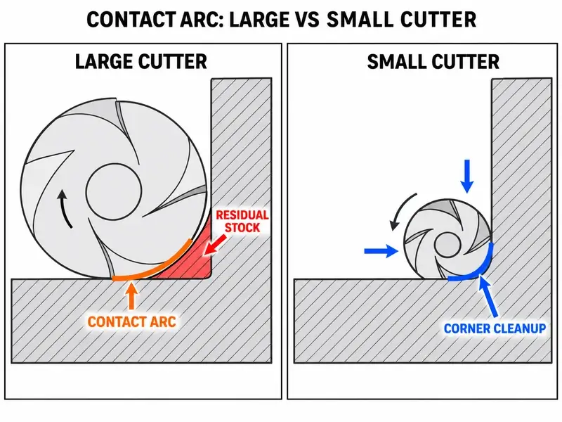
For this kind of rest machining, the useful check is a handoff: the material shape after the large tool, followed by the small tool's contact with that shape. If thick corner stock remains, arrange its removal as a roughing task. If the stock is already even but contact rises sharply in the corner, address the local engagement and approach instead.
If abnormal noise, vibration or tool damage occurs, stop and inspect according to the machine's safety procedure before continuing.
Start with the stock left by the operation that actually ran
Open the material state immediately before the small-tool operation, not just the finished-part model and the toolpath lines. Find the problem corner at the depth where the symptom starts.
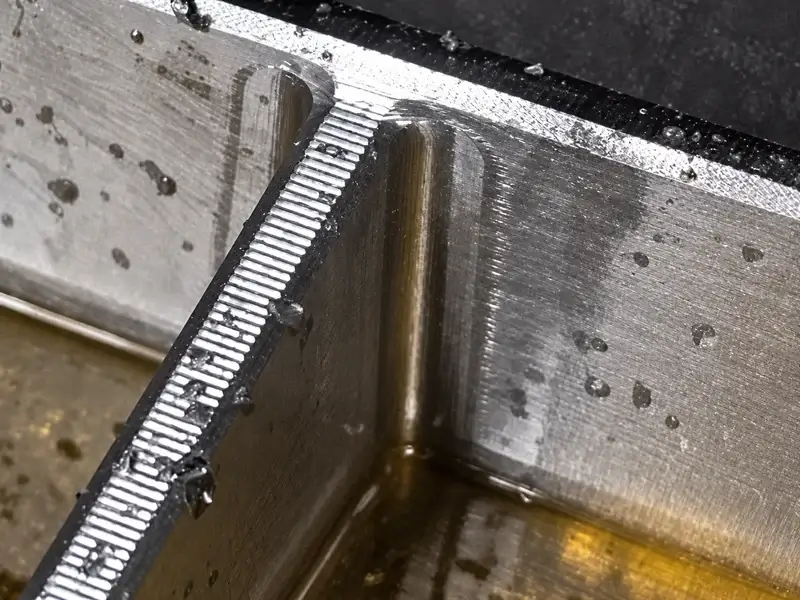
The large cutter may have machined close to the straight walls while leaving a much larger rounded region in the corner. Where its cutting envelope cannot reach the intended smaller internal radius, material remains beyond the planned wall allowance. The next tool therefore moves from a light wall cut into a different stock shape, even though the operation is called “cleanup.”
Check the preceding operation against what happened on the machine:
Was that operation actually run, with the programmed tool, to the programmed depth?
Did a boundary, a deliberate corner blend or an incomplete pass leave material at this location?
Is the displayed stock state taken from that point in the sequence, or from a later operation that has not yet run?
Use the remaining-material view and relevant sections to establish the corner's shape. Do not infer it from the allowance field alone. The allowance is a planned offset; the remaining stock also reflects where the tool and path could reach.
Keep the views separate. The internal corner radius seen from above is not the cutting-edge corner radius on a bull-nose end mill, and neither is the wall-to-floor fillet seen in section. A sidewall pass can reach the wall without removing the stock left around the bottom fillet. Inspect that lower region with the actual tip shape and toolpath coverage in view; a clean wall is not proof of a clean floor junction.
Ask what your rest calculation knows
Rest machining, also called rest milling, targets material left by a previous tool or operation. How that material is identified depends on the specific operation and its inputs. Selecting “rest” does not by itself confirm that the calculation represents the part on the machine.
For example, the rest option in Autodesk Fusion's 2D Adaptive Roughing reference asks for previous-tool information, including diameter and tool corner radius. The selected boundary and the supplied tool geometry help determine which regions need cleanup. If the entered previous diameter or tip geometry does not match the tool used, the estimated uncut region can be wrong.
Fusion's 3D Adaptive Roughing reference offers different rest-stock sources, including previous operations, a file, bodies and setup stock. When previous operations are the source, check that the selected history corresponds to the operations actually completed. When a file or body is the source, check that it represents the correct stage of this part.
Neither approach measures the physical workpiece. A stock model can be useful and still be based on the wrong tool, an omitted operation or the wrong input state. Simulation checks the supplied model and paths; it does not establish actual cutting force, runout or workholding behavior.
Also check what the preceding path intentionally left behind. In Fusion's 3D Adaptive operation, a minimum cutting radius can blend sharp internal turns and leave more corner material for a smaller tool. That can be a sensible roughing choice. It simply creates a later removal task that must be accounted for, rather than disappearing into the finishing allowance.
Follow the small cutter through the corner
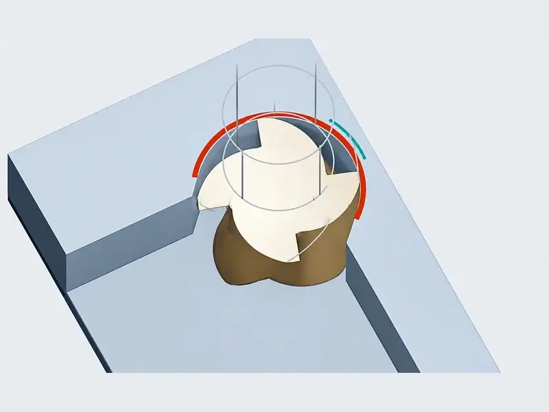
Once the incoming stock is credible, step through the small-tool path at the same location. Look at entry, contact inside the corner and the point where the cutter leaves it. The question is not only whether the centerline turns smoothly, but how much of the cutter meets material along that turn.
Two things can happen together: the tool reaches thicker stock left by the large cutter, and its radial arc of engagement increases as it moves into the corner. The Sandvik Coromant guide to milling inside corners connects that increased engagement arc with greater demands on the cutting edge and a risk of instability or damage.
Remaining stock, radial width of cut and engagement arc describe different things. Stock is the material still present. Radial width describes the width of a cut; engagement arc describes how far around the cutter the material is in contact. A nominal stepover setting is therefore not enough to establish the actual contact throughout a corner.
This is why unchanged spindle speed and feed do not guarantee unchanged load. The small tool may be doing a light trim on the straight, then removing a substantial corner remnant with a larger contact arc. Lowering feed can change the cutting condition, but it does not remove that remnant or change the geometry of the approach.
Use sound to mark where the change starts, not to name its cause. A symptom that begins at one corner is a reason to inspect this local handoff. A symptom that grows with depth or occurs throughout the operation needs a wider investigation.
Match the correction to what you found
If the stock history is wrong, repair the handoff first
Correct the previous-tool definition, stock source or operation selection before tuning the small-tool cut. Recalculate from the intended stage and check it against the workpiece. A path that is safe for a material state the machine never produced is not a useful baseline.
If a thick corner remains, give it a roughing task
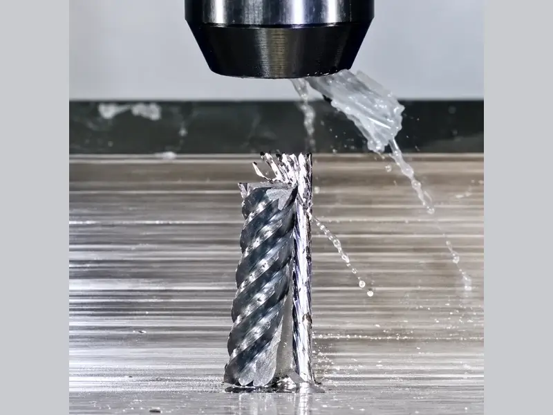
Remove the heavy remnant in controlled stages rather than expecting a finishing-style pass to swallow it. Depending on access and the generated path, this may mean multiple radial passes, separate depth levels or an intermediate cutter that removes a useful share of the stock before the smallest tool enters.
An intermediate tool earns its place by reducing the difficult cut. It is not mandatory wherever a smaller cutter follows a larger one. If the preceding operation already leaves an even allowance and the small tool's contact is controlled, adding another tool may contribute little. Broader sequencing and chip-management choices belong in the overall pocket milling process.
Decide separately whether this rest operation is preparing for finishing or producing the final feature. In the former case, preserve the planned later allowance and assess when a separate semi-finishing operation is worth adding. In the latter, meet the drawing. The word “cleanup” does not determine either the load or the required remaining stock.
If the stock is even but contact still spikes, change the local approach
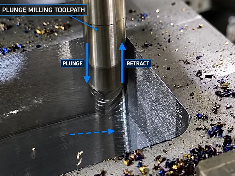
Inspect whether a smoother transition, a different approach direction or a path that limits corner engagement reduces the abrupt contact. Judge the path that is actually generated, including how it enters and leaves the remaining material. A smoother-looking centerline alone is not the acceptance test, and slowing all the straight sections does not correct a local geometry change.
Before testing the revision, match the physical small tool to the program: diameter, tip geometry, usable cutting length and stickout. Check shaft and holder clearance as well as tip access. Then select cutting conditions for that tool, material, reach and setup. There is no single corner-feed reduction or stepover that follows from the diagnosis above.

Prove the new handoff at the same location
Keep the verification focused enough to tell whether the change worked:
Recheck the stock immediately before the small tool. Confirm that the heavy corner remnant has either been removed or divided into the intended cuts.
Step through entry, the inside of the corner and exit. Confirm that the revised path addresses the contact change you identified, rather than merely moving it to another point.
Under the site's approved prove-out procedure, evaluate the same feature while keeping unrelated changes out of the trial. Compare the surface and cutting-edge condition as well as sound and chip evacuation.
Check the resulting wall, corner and bottom geometry against the drawing. Reduced noise does not prove that the required material was removed or that the feature is in tolerance.
If the stock handoff and local contact are now credible but instability persists more broadly, move on to a systematic milling chatter diagnosis instead of repeatedly reworking this one corner assumption.
The small cutter should inherit a defined removal task—not an unseen pocket of stock hidden behind a nominal allowance.