


Chip Evacuation in Pockets: Find Where the Chips Stop
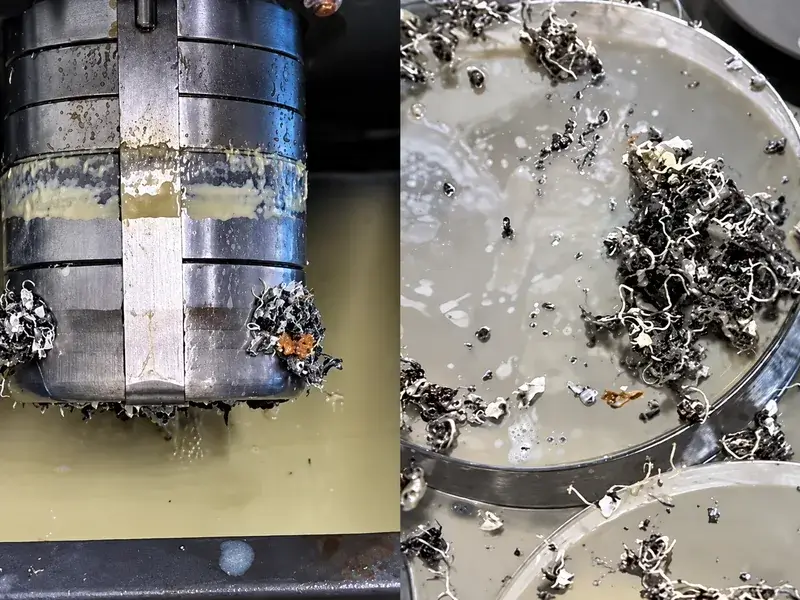
If a pocket clears well with one tool but starts packing chips after a tool change or a deeper pass, compare those two cutting positions before increasing coolant flow. The nozzle may no longer reach the working area. Or it may reach the cut perfectly well while pushing the chips into a place they cannot leave.
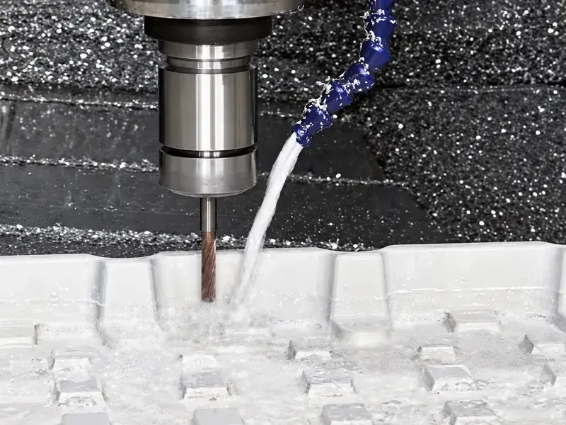
Those are different chip evacuation problems. Moving chips away from the cutting edge is only the first part of the job; leaving them where the next pass will pick them up is not sustained evacuation.
Observe through the machine's intended guarding and use its prescribed safe stop and isolation procedures for adjustment or chip removal. Do not open the enclosure for a better running view, reach into the machine or follow the cutter with a handheld air gun. Any air or mist assistance also needs suitable flying-chip and aerosol control.
Find the transition from clearing to packing
Use the last position that clears properly as a reference. Then identify the first tool, depth and path segment where chips begin to remain. “The pocket fills up” is less useful than “the buildup starts at the far wall after the tool moves down to the next level.”
For each position, record where the stream actually strikes and where the displaced chips go next. Does the jet hit the cutting region, the holder, a wall or the top of the workpiece? Do chips leave the cavity, collect behind an island or drift back into the cutter's next path?
A nozzle setting that works for a short tool may miss the cutting region after a longer tool is loaded. A stream that reaches the near side of a shallow pocket may be screened by a wall when the cutter moves deeper or farther away. Check the tool in the position where the problem occurs, not only above the part or at the start of the operation.
If the cutting region cannot be seen safely, do not record coolant arrival as confirmed. Use the available protected observation method and stopped inspections to establish what you can. Wet walls and a flooded floor do not establish where the moving stream is acting.
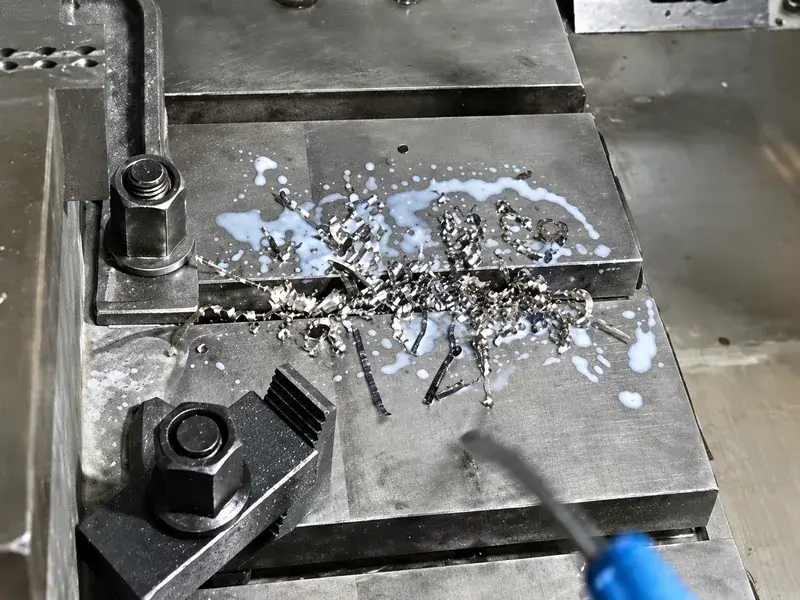
Use the chip movement to choose the next action
The following checks separate a delivery miss from a downstream transport problem. They are diagnostic directions, not a prescribed nozzle arrangement.
| At the problem position | Check next | Targeted action |
|---|---|---|
| The stream strikes the holder or an obstruction rather than the working region | Compare nozzle aim and obstruction with the last clearing position | Correct the reachable delivery route and verify it for this tool and depth before increasing supply |
| Chips leave the edge but circulate, settle in a corner or collect in the next pass | Follow their route from the cut to an actual exit from the cavity | Change the flushing direction or verified clearing sequence so chips leave, rather than move to another cutting location |
| The stream reaches the cut and an outward route exists, but retained chips keep increasing | Check actual supply condition and whether chip production exceeds the current removal capability | Restore a restricted supply or revise the validated cutting/clearing process; do not assume a pressure increase is the answer |
For a delivery miss, make the nozzle correction specific to the tool. Haas's P-COOL operation procedure, for example, determines a spigot position for each tool and calls that position with the tool offset. It illustrates why the previous tool's setting should not be accepted without checking. It does not guarantee an unobstructed route inside every pocket. P-COOL is motorized: Haas explicitly says not to move its spigot by hand; use the prescribed control commands.
Once arrival is established, stop using the cutter as the endpoint of the check. Follow the chips beyond it. A jet can clear the edge while driving chips against the opposite wall. They may then settle in the cavity or return across the next cutting path. A rising liquid level can coexist with that circulation.
Look for a usable route past the existing cavity walls, islands and workholding. A better flushing direction may carry chips toward an available opening rather than into a dead region. Where a programmed clearing opportunity is needed between cuts, include it in the verified sequence instead of relying on an operator to chase the tool. This is not permission to add holes to the part or alter drawing features or safe clamping arrangements.
If arrival and the outward route remain effective but chips still accumulate, check what the system is actually delivering: available fluid level, restricted filters, blocked nozzles and the relevant equipment condition. Follow the equipment and fluid suppliers' procedures. Broader fluid selection and maintenance belong in the cutting fluid guide, not in a guess at a new concentration for this one pocket.
Also compare chip production with removal. A route that handles the earlier pass may not handle the later cutting stage. Inspect chip form and flute loading rather than assuming the pump is the only limit. If the delivery route is credible but aluminum continues to adhere or pack in the flutes, review the aluminum end mill selection and chip-space considerations. That is a different decision from simply aiming more liquid at the tool.
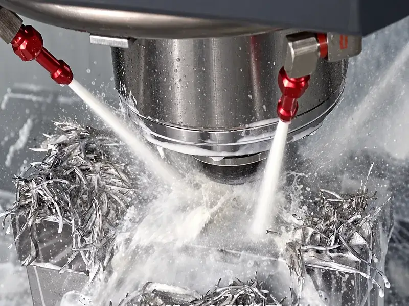
If external delivery cannot keep a route to the cut
When the working depth or obstructions prevent an effective external stream, assess a delivery method that the machine and tool actually support. Through-tool coolant can bring fluid closer to the cutting region in a compatible system, but chips still need a route out of the cavity. It does not remove the second half of the diagnosis.
Air assistance can move chips where appropriate, but it does not supply lubrication. The distinction is explicit in Harvey Performance's coolant-delivery guidance. An aluminum operation that needs lubrication must retain an appropriate means of providing it; an air stream is not automatically an equivalent replacement. Nor is higher pressure a universal upgrade: the same guidance warns that it can damage miniature tooling. Check the tool and equipment limits rather than choosing a pressure from a generic category.
Do not lengthen the cutter merely to give a nozzle a clearer line of sight. Solve the delivery access without casually increasing reach and reducing rigidity.
A change of delivery method must also suit the cutting process. Sandvik Coromant's dry and wet milling guidance discusses thermal cycling in interrupted milling alongside material- and operation-specific reasons to use fluid. If chipping appears after a delivery change, review the thermal-cycling and coolant-supply checks. Do not turn an evacuation problem into a blanket instruction to intermittently wet every carbide milling cut—or, conversely, to dry-mill every aluminum pocket. Use the requirements for the actual tool, material and operation.
Test beyond the first clear pass
Change the condition tied to the observed failure and keep the comparison meaningful. Document the starting chip condition and compare equivalent portions of the cut. An empty pocket immediately after cleaning is not evidence that a nozzle change will prevent the original buildup from returning.
Revisit the original problem position, then continue through the subsequent passes that previously caused accumulation. Confirm that the stream still reaches the working region as the cutter moves and that displaced chips keep leaving the cavity. Check whether a heap develops where a later pass or the next tool will cut. A clear patch around the current edge is not enough if the process merely moves the pile ahead of itself.
Compare retained chips, visible recutting marks on the surface and cutting-edge condition. Sound is useful supporting information, not the acceptance criterion. If the cut is quieter but the same pocket of chips returns, the transport problem remains. If arrival has improved but chips now stop against another wall, the first link was corrected and the downstream link still needs work.
Successful chip evacuation means maintaining a usable route as this cavity, tool position and cutting sequence change—not producing the largest splash at the start.