


Climb vs Conventional Milling: Differences, Risks, and When to Use Each
For climb vs conventional milling, start with climb on a rigid CNC machine with controlled backlash, secure workholding, a suitable cutter and clean stock. Start with conventional on an older or manual machine when backlash can let the axis self-feed, or when the cutter must enter through a hard scale or surface skin. That is the useful answer—but it only works after you understand which side of the cutter is engaged and where the cutting force will go.
Climb is not automatically “professional” and conventional is not obsolete. They form chips in opposite directions, place chips differently, and load the machine-workpiece system differently. Those differences affect finish, rubbing, heat, workholding, tool deflection and safety.
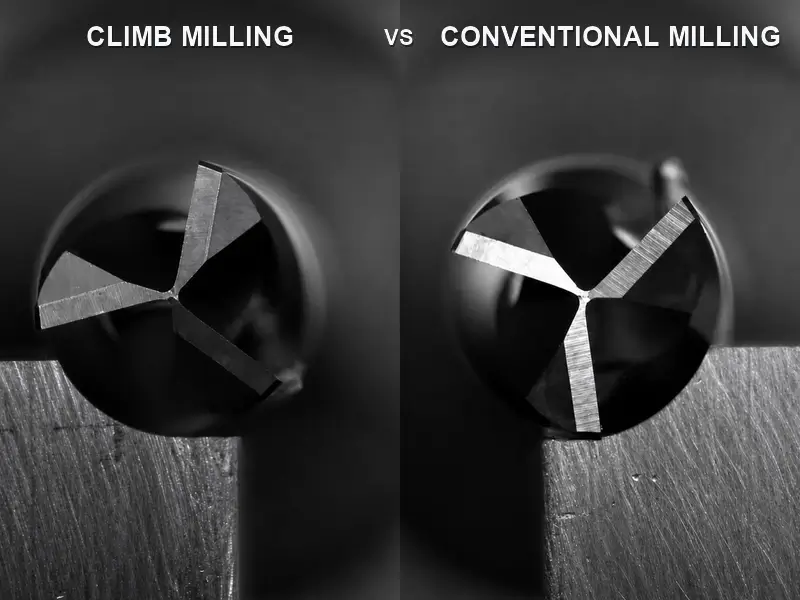
The difference starts at chip formation
The names describe the relationship between cutter rotation and feed at the engaged cutting edge.
In climb milling, also called down milling, the cutter surface at the point of engagement moves in the same direction as feed. A tooth enters at or near maximum chip thickness, then the chip becomes thinner as the tooth exits.
In conventional milling, also called up milling, the cutter surface at engagement moves against feed. A tooth begins near zero chip thickness, rubs or ploughs until it starts cutting, and the chip becomes thicker toward exit.
Do not define the methods as “clockwise versus counterclockwise.” A standard right-hand end mill may keep the same spindle rotation while the toolpath direction changes around the part. On an external contour, reversing path direction swaps climb and conventional. On an internal contour, the physical travel direction that produces climb reverses relative to the outside wall.
The thick-to-thin versus thin-to-thick distinction drives most of the comparison. Climb loads the tooth more abruptly at entry. Conventional develops force more gradually but spends more of the entry phase at very small chip thickness.
To identify the direction on a real path, pause at one point on the wall and draw the cutter as a circle. Mark the local surface velocity of the engaged flute from spindle rotation, then mark feed direction. If the two arrows point the same way at contact, the pass is climb. If they oppose, it is conventional. Repeat this check whenever the tool moves from an outside wall to an inside wall; the answer changes even when spindle rotation does not.
This local method also prevents a common CAM mistake. The tool-center path can look clockwise on screen while the engaged cutting edge is behaving differently because the path is internal rather than external. Direction belongs to the cutter-work contact, not to the apparent orientation of the overall shape.
Climb vs conventional milling at a glance
| Dimension | Climb milling | Conventional milling | Decision implication |
|---|---|---|---|
| Tooth motion at engagement | Moves with feed | Moves against feed | Identify the engaged side, not just spindle rotation |
| Chip thickness | Maximum toward entry, then decreases | Starts near zero, then increases | Climb reduces the low-thickness entry phase; conventional softens force onset |
| Chip placement | Tends to leave chips behind the cutter | Tends to carry chips toward the area ahead of the cutter | Conventional can increase recutting risk if evacuation is poor |
| Force tendency in the common peripheral model | Pulls the cutter/work together and includes a downward component | Opposes feed and includes an upward component | Climb demands backlash control; conventional demands strong anti-lift workholding |
| Typical finish on qualified CNC | Often the first choice | Can rub or recut chips, but may still solve a specific stability problem | Treat finish as conditional evidence, not a guarantee |
| Machine boundary | Best suited to rigid, backlash-controlled motion | Safer baseline when feed screws have play or the axis may self-feed | Machine condition can override every other advantage |
| Surface-layer exception | Tooth strikes the outer layer at high chip thickness | Tooth can approach from below the surface layer | Rough scale or hardened skin can favor conventional entry |
The force descriptions are tendencies from the documented peripheral/horizontal model. Helix, engagement, contour side, holder, stickout and workpiece geometry change the complete three-dimensional load. Use the table to frame the choice, then evaluate the actual setup.
Why climb is usually the CNC starting point
Modern CNC machines normally control axis motion with preloaded or compensated systems that minimize lost motion. Under those conditions, climb milling offers several useful mechanisms.
First, the tooth starts by cutting a real chip rather than entering at nearly zero thickness. That reduces the rubbing phase associated with conventional entry. In materials prone to work hardening or edge glazing, less rubbing can matter.
Second, chips tend to leave behind the cutter instead of being deposited in front of the next tooth. Better chip separation reduces the chance of recutting, although air, coolant and flute space still control whether chips truly leave the cutting zone.
Third, the common force tendency can press the work toward its support rather than lift it. On a securely supported plate or floor-finishing operation, that direction may help. It does not rescue a weak fixture, and it may be harmful if the force bends a thin wall into the tool.
Fourth, the combination of less rubbing and less chip recutting often gives climb a surface finish advantage on qualified CNC equipment. A documented shop case in 6061 aluminum describes a clean climb-milled side and chips embedded in the conventional-milled surface. That is useful failure language: it points to chip flow and recutting. It is not proof that every aluminum cut must climb.
Roughing and finishing still ask different questions. In roughing, stable engagement, chip clearance and tool load may dominate the choice. In finishing, the surface finish and the direction of elastic recovery matter more because a small deflection can become the final wall error. It is reasonable to rough with the direction that keeps the process stable, leave controlled stock, and qualify the finish direction separately rather than forcing one direction to perform both jobs.
Use climb as a starting direction when all of these conditions are true:
- axis backlash is controlled;
- servo and drive behavior are sound;
- holder, spindle, tool and workholding are rigid enough for the entry load;
- stock does not present a hard scale or unknown skin;
- chip evacuation keeps the cut clear;
- CAM produces a consistent direction where finish matters.
Backlash is the hard safety boundary
Backlash is lost motion between a command or handwheel movement and actual axis response. On a worn lead screw and nut, direction can reverse through a zone where the screw turns but the table has not yet been positively driven.
Climb cutting force acts in the feed direction. If that force can pull the table across the backlash gap, the cutter can suddenly take more engagement than commanded. The axis is no longer being metered only by the screw; the cut is helping move it. Shop descriptions of the event are appropriately blunt: handwheel force falls as the cut begins to self-feed, then the table can jump, chip the tool, damage the part or endanger the operator.
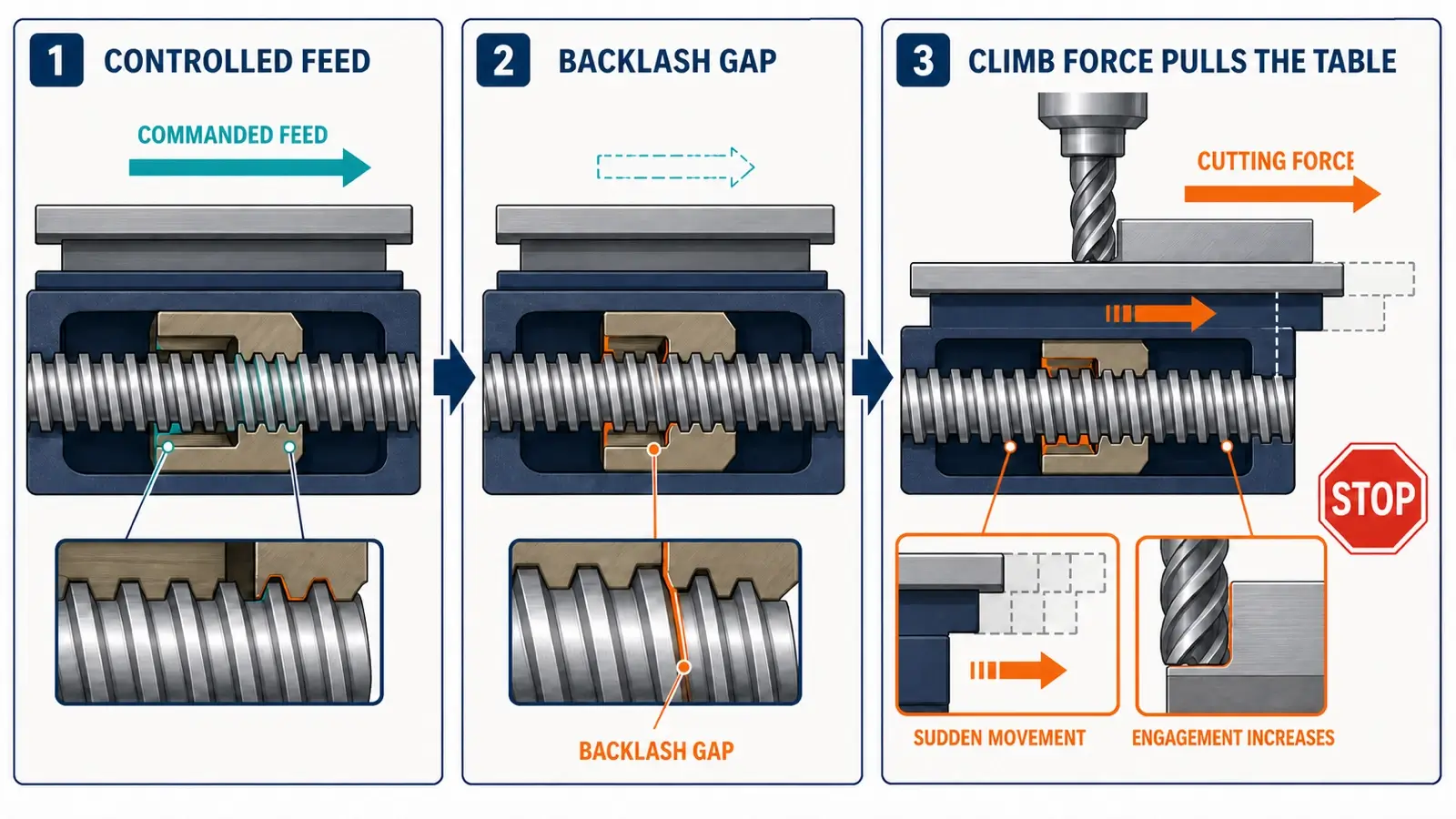
Conventional force opposes feed. On the same worn manual machine, that resistance tends to keep the screw and nut loaded against one side of the clearance. This is why conventional has traditionally been the baseline for machines without reliable backlash control.
There is no universal safe backlash number. Risk changes with cutter diameter, flute count, radial engagement, depth, material, helix, sharpness, table resistance, feed-screw condition and operator control. A small measured value does not certify safety for a heavy cut, and a previous successful light pass does not prove a deeper pass will behave the same way.
Software compensation and mechanical control are not the same thing. A control may correct commanded position when an axis reverses, but that setting alone does not prove cutting force cannot pull a loose mechanical system through clearance. The relevant question is whether the drive keeps the axis positively controlled throughout the intended cut.
This also explains why advice transfers poorly from one “Bridgeport-style” machine to another. Two machines can show similar indicator backlash yet differ in way friction, screw condition, table mass and how heavily the cut loads the axis. Qualification belongs to the specific machine and operation.
Before climb milling on a manual or uncertain machine:
- measure and understand each axis’s lost motion;
- verify whether the machine has an effective backlash eliminator or preloaded drive;
- check whether the axis can be pulled through the handwheel under cutting load;
- use table locks or drag only according to the machine’s proper operating method;
- avoid using a production cut as the experiment that discovers self-feeding.
If the handwheel becomes unexpectedly light, the axis surges, or engagement increases without command, stop. Do not “feed through” to see whether it settles.
When conventional milling is the deliberate choice
Backlash is the clearest reason, but not the only one.
A rough casting, flame-cut edge, mill scale or hardened outer skin can favor conventional entry. In climb, the tooth encounters the outer layer at the thick end of the chip, with material behind that layer supporting it. In conventional, the tooth can start in the softer underlying material and approach the surface layer near exit. The exact advantage depends on surface condition and cutter, but it is a real exception to the clean-stock climb default.
Conventional can also help when the abrupt entry load of climb excites a flexible system. Because chip thickness builds from near zero, force onset is more gradual. That does not make conventional inherently chatter-free: rubbing at entry and upward force can create different instability. It means direction is a legitimate diagnostic variable when the setup reacts badly to climb entry.
Some machinists use a controlled conventional spring or finish pass to influence deflection direction. Treat that as a geometry-specific technique, not a recipe. The wall side, toolpath direction, stock remaining and tool bending determine whether the edge cuts toward or away from the target surface.
Certain cutters and operations also require specific guidance. Slitting saws, keyseat cutters, form tools and interrupted surface conditions should follow the toolmaker and machine procedure. Do not generalize a peripheral end-mill rule to every cutter body.
Cutting force is a vector, not a slogan
“Climb pushes down; conventional lifts up” is useful only as an entry point.
The cutter experiences tangential and radial force components. A helical flute adds an axial component. Which way those components bend the tool and workpiece depends on the engaged side and local toolpath direction.
For a thin floor, downward force may support the material if it rests firmly on a fixture. If there is a cavity underneath, the same force may deflect the floor. Upward force may lift sheet stock from supports or pull it against a clamp. Neither label replaces checking support direction.
For a thin wall, decide whether radial force pushes the wall away from the tool or pulls/bends it toward the tool. Then consider how tool deflection moves the cutting edge. A roughing path may intentionally leave stock and choose the direction that reduces gouging risk; a finish path may reverse direction on the opposite wall to keep the deflection effect consistent.
For weak workholding, conventional’s upward tendency can be a serious problem. Climb’s pulling action can also shift a part if the fixture does not resist horizontal load. Secure the part against every significant force component, not merely vertical lift.
For long stickout, small diameter or slender tools, the direction that gives the best theoretical chip can still produce poor dimensional control if radial deflection dominates. Reduce the cause—stickout, engagement, rigidity or inappropriate geometry—rather than expecting direction alone to cure it.
Tool geometry still matters
Cut direction does not determine flute space, helix, coating or edge preparation. A conventional pass with excellent evacuation may outperform a climb pass that packs chips, and a climb pass cannot make a steel-oriented high-flute tool ideal for an aluminum slot.
Confirm:
- right-hand or left-hand cutter and spindle rotation;
- up-cut, down-cut or compression geometry where those terms apply;
- flute count and chip-gullet volume;
- helix and axial-force tendency;
- edge sharpness and corner condition;
- runout, holder condition and stickout;
- coating and work-material compatibility;
- whether the operation is slotting, side milling, facing or profiling.
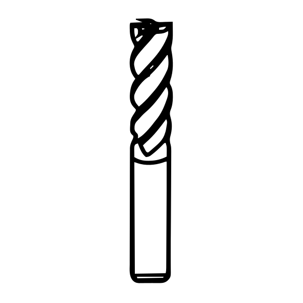
The solid carbide end mill can be used to navigate cutter families while planning the operation. It does not prove that a specific geometry, coating or direction suits the cut; verify the exact product data.
For slotting and peripheral profiling, a carbide flat square end mill is one geometry to evaluate alongside material, engagement and chip evacuation.
Keep “down milling” separate from a “down-cut end mill.” The first describes feed direction relative to cutter rotation. The second describes flute geometry and axial chip/force direction. Mixing the terms can lead to a toolpath that is labeled correctly but behaves differently from what the programmer expected.
Internal contours, external contours, slots and mixed CAM direction
On an external contour with a standard right-hand cutter, one travel direction produces climb on the outside wall; reversing travel produces conventional. On an internal pocket wall, the relationship reverses. Program from the engaged side and spindle direction rather than memorizing “clockwise is climb.”
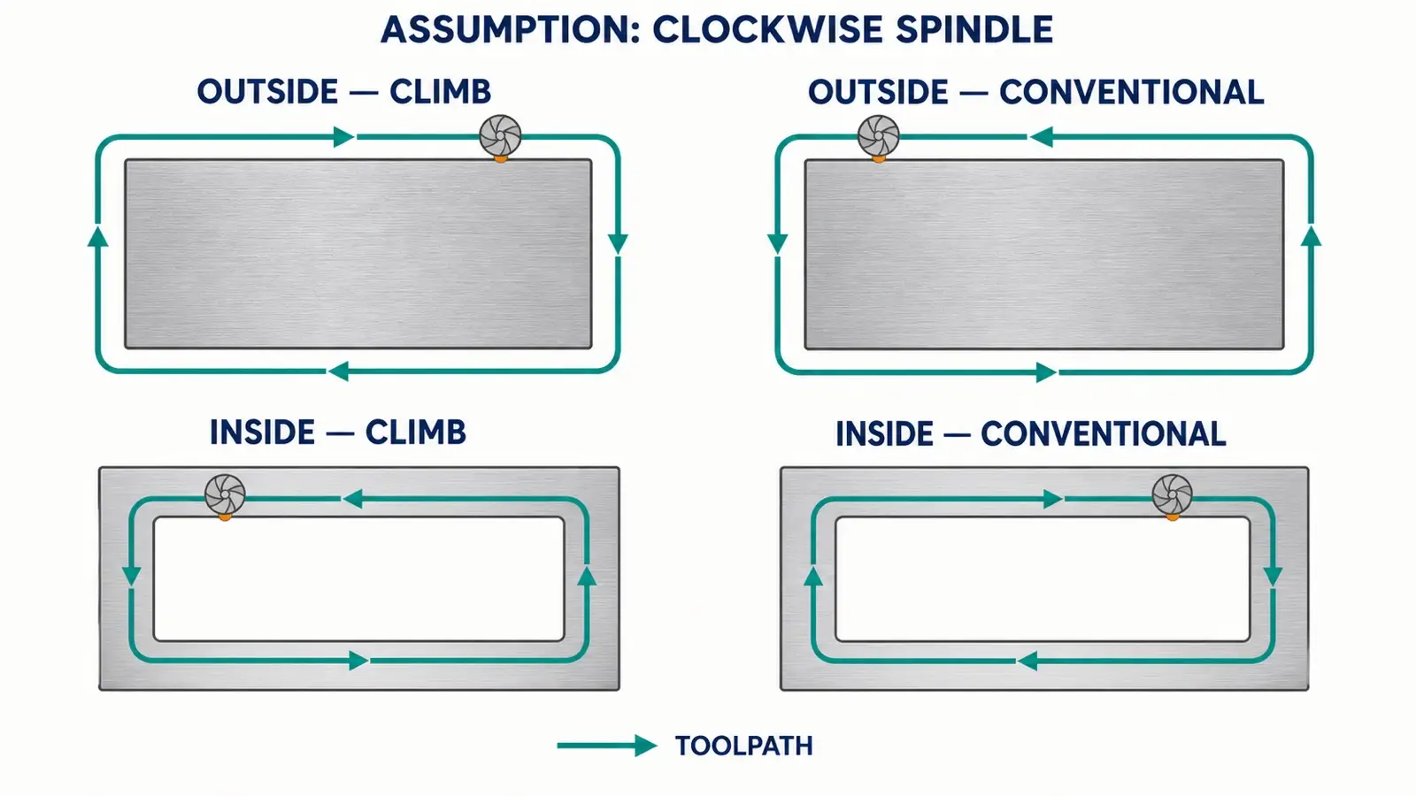
In a full-width slot, one side of the cutter is climbing while the opposite side is conventional. The cut cannot be classified as purely one or the other. Chip evacuation, flute count, radial force balance and tool deflection become more useful controls than a single direction label.
During adaptive or trochoidal paths, engagement moves around the cutter. CAM normally maintains a chosen direction at the active side, but lead-in, linking and corner transitions can change local load. Inspect the generated toolpath rather than trusting only the operation name.
Mixed-direction CAM alternates climb and conventional to reduce non-cutting travel. It may be useful in roughing where motion efficiency matters more than uniform witness marks. For finishing, alternating direction can create visible changes in texture, load and deflection. If the surface matters, a consistent one-way pass is usually easier to qualify.
Review lead-ins and lead-outs as part of that decision. A finish contour may be set to climb, yet an automatic linking move can touch the wall conventionally before the main pass or leave a witness at the entry point. Place the lead where the surface can tolerate it, confirm the cutter reaches stable engagement before the critical wall, and inspect the simulation at corners and narrow regions rather than only along the longest straight segment.
When the CAM system offers “keep tool down,” “shortest path” or similar optimization, verify whether it is allowed to reverse cutting direction. Saving a retract can be valuable, but it should not silently trade away a qualified surface strategy.
Rest machining and cleanup moves deserve the same attention. A tiny leftover region can produce a much larger local engagement than the main path. The fact that CAM labels it climb does not make the entry load harmless.
Troubleshoot the direction before changing every parameter
If conventional milling leaves a smeared or chip-marked surface, inspect where chips are being thrown and whether the next tooth recuts them. Improve evacuation, verify chip formation and compare a controlled climb pass if the machine qualifies.
If climb milling grabs or the axis jumps, treat it as a backlash or motion-control problem. Stop the cut. Do not solve it by lowering feed until the event feels less violent; a self-feeding mechanism remains unsafe.
If climb chatters at entry but conventional becomes stable, inspect rigidity, engagement and the abrupt thick-chip entry. Reduce the destabilizing condition and retest one variable at a time. Do not conclude that conventional is globally superior from one flexible setup.
If a thin wall tapers or bows, map the radial force and tool-deflection direction on that specific side. Compare roughing and finishing stock, toolpath direction and support. Reversing the pass may move the error rather than eliminate it.
If both directions give poor finish, direction may not be the primary cause. Check runout, worn edges, built-up material, chip recutting, holder condition, stickout, workholding, coolant delivery and whether the programmed chip load is actually being achieved.
If conventional causes rapid wear or a polished-looking edge, the near-zero-thickness entry may be rubbing. Confirm feed per tooth and edge condition before simply increasing speed.
If climb damages a scaled surface or chips the edge on entry, test whether the outer layer is the dominant problem and whether a conventional entry or separate scale-removal operation is appropriate.
Record each trial with direction, engaged side, radial and axial engagement, RPM, feed, tool, stickout, material condition and observed symptom. Change one variable at a time. Otherwise, a better finish cannot tell you whether direction, evacuation or a simultaneous parameter change produced it.
Conclusion
Climb milling is the normal starting point on a rigid CNC machine with controlled backlash, clean stock, secure workholding and suitable geometry. Conventional milling is the deliberate choice when backlash can let the axis self-feed, when a hard surface layer changes tooth entry, or when the actual force-onset and deflection behavior favors it.
Choose from the machine and cut, not from a slogan. Identify the engaged side, follow the chip from entry to exit, map the force into the tool and workpiece, and stop immediately if climb motion begins to pull an axis beyond commanded feed.