


Cutter Radius Compensation: Check What CAM Has Already Offset
Before changing a wear value to correct a milled size, establish whether CAM has already included the nominal tool-radius offset in the posted coordinates. The controller may be expected to supply the full offset, only a small correction, or no radius compensation on that pass. Those are different starting points.
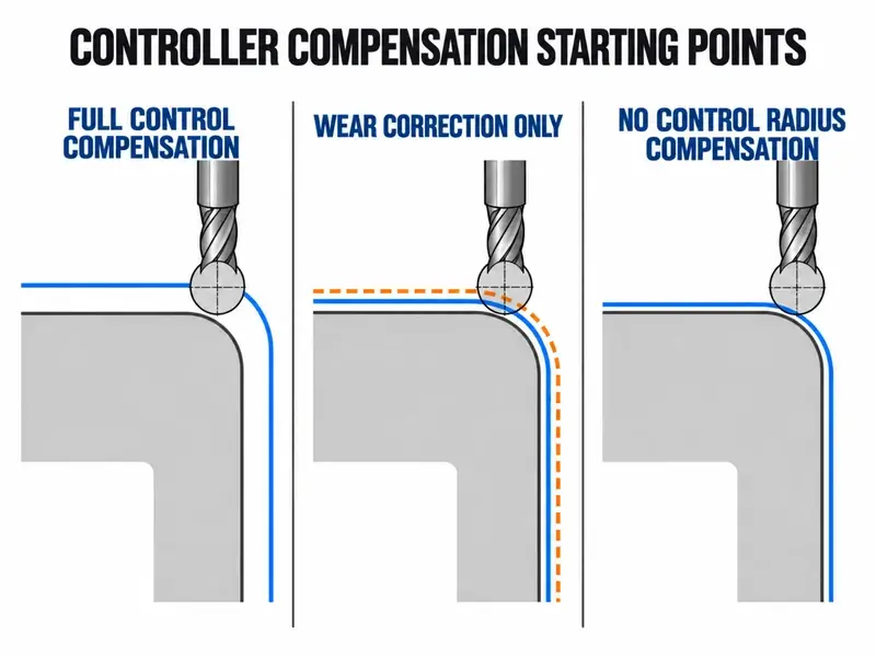
Seeing G41 or G42 does not settle the question: both full control compensation and CAM-generated wear compensation can use them. The reliable starting check is the same finishing operation traced through CAM settings, posted NC and the active controller offset.
Identify who owns the nominal radius offset
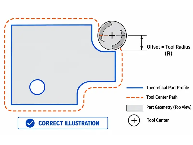
The finished profile and the tool-center path are not the same geometry. Something must account for the cutter's radius—but it need not be the controller. A CAM system can calculate an offset path before the program reaches the machine.
Fusion's 2D Contour documentation makes the distinction explicit:
| Fusion compensation mode | What CAM has already done | Intended controller role |
|---|---|---|
| In computer | Calculated the radius offset from the selected tool diameter and posted the offset path | This mode posts the path instead of G41/G42 compensation calls; do not assume a wear-table edit will move it |
| In control | Left the tool-radius offset calculation to the control | Apply the required offset through the emitted compensation call and the machine's offset data |
| Wear | Calculated the nominal offset as in computer, while also emitting compensation calls | Apply the difference needed for size correction, not the nominal radius a second time |
| Inverse wear | Used the same nominal-offset approach as Wear | Apply the correction using this option's different sign convention |
| Off | Applied no radius offset; the tool center follows the selected geometry | There is no radius correction supplied by this option to substitute for the missing offset |
These are Fusion labels for the documented 2D operation, not a universal menu shared by all CAM systems. Its documentation also limits control compensation, including Wear and Inverse wear, to finishing passes in this context.
The duplication risk is clearest in Wear: if CAM has already shifted the path for the nominal cutter and the controller then adds a full nominal-radius amount where only a correction was expected, the same task has been performed twice. Do not diagnose that from a mode name alone; confirm what was posted and what the machine actually applies.
Prove what the posted finishing pass actually uses
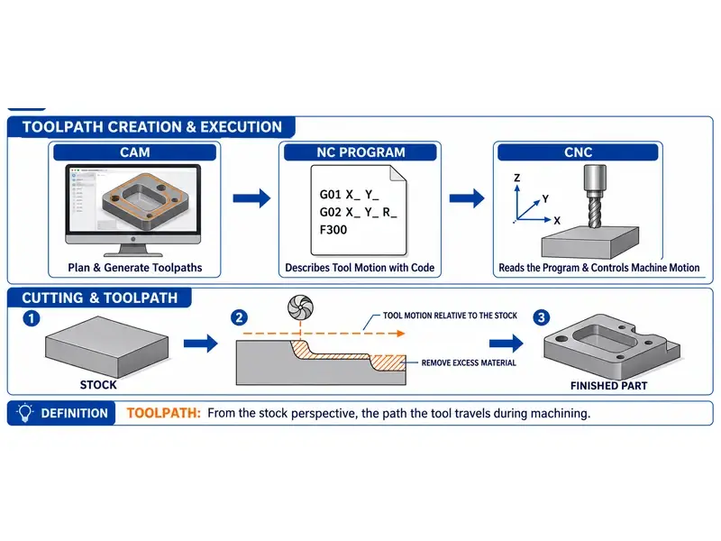
Start with the CAM operation that made the measured surface. Record its compensation type, programmed tool diameter, stock-to-leave and finishing-pass settings. Confirm the intended controller and post processor, then identify the exact posted file being run—not an earlier output or an unsent revision.
Inspect the relevant pass with its surrounding activation and cancellation moves. Check the active plane, compensation side and selected offset number. Compensation can remain active from an earlier block, so the absence of a call on the line under the cursor is not proof that it is off.
Compare the posted path with a known portion of the selected geometry, accounting for tool size and any remaining allowance. A verified backplot or program inspection should establish whether the nominal radius is already represented in the coordinates and what is left for the control. A CAM preview by itself does not prove the state of the machine's active register.
Then match the register you intend to edit to the offset actually selected for that pass. A correct-looking value in another row—or on a roughing operation that does not use the same correction—will not produce the expected finishing change.
If the pass has no active controller radius compensation, changing that radius/wear register is not a route to adjusting it. Correct the identified CAM/post workflow and regenerate and verify the output as required. Do not add G41/G42 to an unfamiliar path simply to make the wear column respond; activation, lead-in and contour clearance also have to work.
Read the effective offset, not just the wear cell
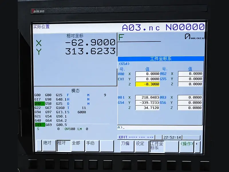
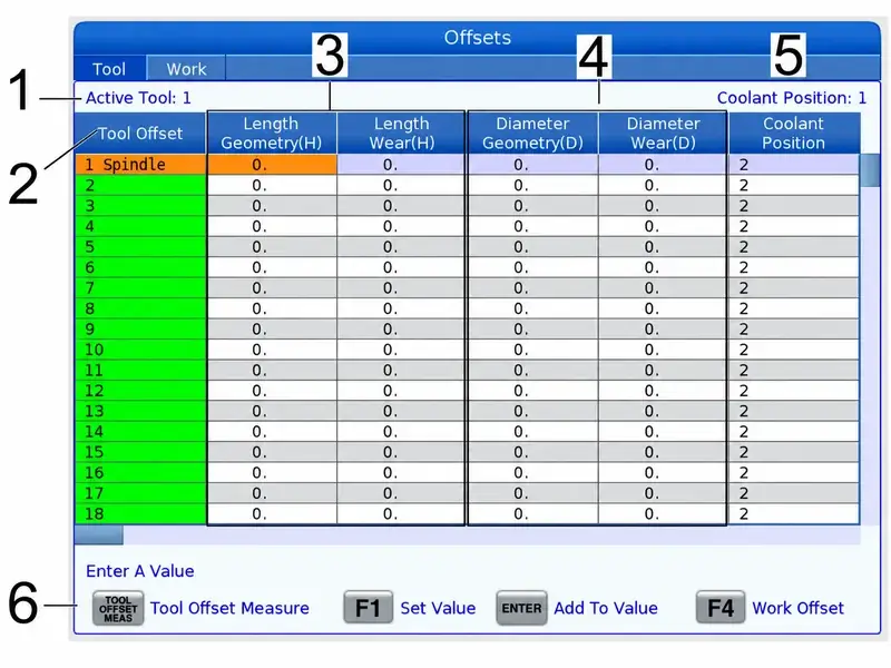
On the documented Haas mill control, the effective offset is the geometry value plus the wear value. Setting 40 determines whether both entries represent radius or diameter. In diameter mode, the corresponding lateral path shift is half the entered effective amount; in radius mode, it uses the radius amount.
The D address selects the offset number. It does not, by its letter alone, tell you that the entered number is a diameter or that the active row contains the expected value.
This matters when a CAM Wear operation is paired with machine data. The CAM option describes the intended division of compensation; it does not mean the controller ignores its geometry column. Inspect the effective total and reconcile it with the posted path. Do not automatically zero geometry fields across a machine or assume an old full-size entry is harmless.
Haas also documents reversed side behavior for a negative effective offset. That is not the same statement as “a negative number in the wear column reverses compensation.” A negative wear contribution can leave the geometry-plus-wear total positive. Check the total, not one cell in isolation.
These setting and field rules are Haas-specific. Another controller's manual and configuration must establish its effective amount and entry scale; a Fusion mode name cannot supply those facts.
Convert intended wall movement before choosing a sign
First describe the required movement geometrically: which finished wall must move, in which normal direction, and relative to what datum or opposite wall? “The size is oversize” is not yet a controller instruction. An outside profile and an internal opening do not map that description to the same tool-center movement.
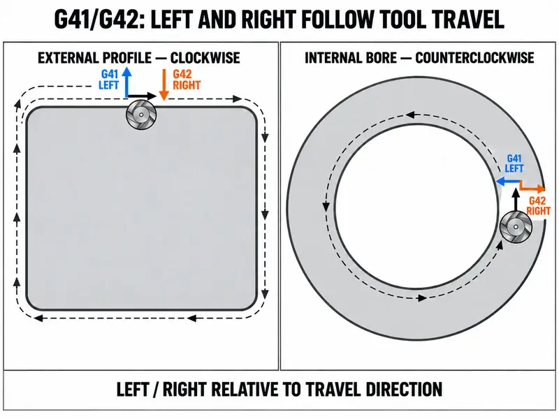
Next follow the programmed travel direction in the active compensation plane. In the Haas G17/XY explanation, G41 and G42 select left and right relative to that travel—not fixed screen-left and screen-right. Combine the actual direction, selected side, effective offset and CAM/post convention before choosing an entry sign. Fusion's separate Wear and Inverse wear choices are another reason not to borrow a sign rule from a different setup.
There are also two separate scale conversions: field change to lateral path shift, then path shift to the measured feature. For ideal geometry where a normal shift transfers equally to the finished boundary:
If one boundary moves by magnitude
sand the reference boundary stays fixed, the separation changes bys.If two opposing boundaries move equally in opposite directions by
s, the width changes by magnitude2s.For a circle, a radial boundary change of
schanges the diameter by magnitude2s.
Those are geometric magnitudes, not machine-entry formulas. Before using them, establish which surfaces this pass actually changes and whether they move symmetrically. Then apply the register's radius/diameter definition. The Haas diameter-entry factor and the feature's two-sided factor are different relationships; “divide every measured error by two” skips that distinction.
Make one reversible test, then compare the same feature
Save the original program revision and offset values, including the effective total and field scale. Use the machine's verification and trial procedures, keeping physical access to a safely stopped machine. Make one correction within the path's verified compensation range; the available lead-in, lead-out and contour space must still accommodate the changed path.
Record the old value, new value, predicted movement and measured response. Re-measure the same feature at the same locations with the same method. Check that the response has the expected direction and scale before making another adjustment. Graphics or simulation can check a path, but they do not replace the finished-part measurement.
Stop stacking offsets if the feature does not respond, moves the opposite way, changes unevenly with position or height, or needs a correction outside the verified range. Return to the active pass, register and scale checks first. If those agree, investigate the physical machining or measurement problem separately using the deflection, remaining-stock and overcut distinctions. A uniform offset cannot generally cure a tapered wall or local remaining stock, and it cannot put back material already overcut.
The useful result of the test is not merely a new number in the wear table. It is a confirmed relationship between this posted operation, this active offset and the measured feature's response.