



Deep Hole Drilling Techniques: Pilot, Coolant and Long-Drill Entry
A long carbide drill can fail before it reaches the difficult part of the hole. If its entry is unstable, increasing coolant pressure or reducing the cutting feed later in the cycle will not correct the beginning of the process.
For long, through-coolant solid carbide drills on machining centers, entry is a separate operation from deep cutting: prepare a suitable pilot hole, introduce the long drill using the specified entry routine, then begin the deep cutting portion. Check the machine's coolant delivery before running that sequence. Where the tool system calls for an intermediate-length drill, include it deliberately.
The techniques below concern that process. Gun drilling with a guide bush, other deep-hole systems and microdrilling need their own procedures.
Define the depth and reach before choosing the sequence
Keep hole depth, flute length and overall tool length separate. A 5 mm diameter hole that is 100 mm deep has a depth-to-diameter ratio of 20:1. A drill with 100 mm of flute length does not automatically have 100 mm of usable drilling depth: point geometry, clearance and the tool's specified capacity also matter. Shank length does not count as usable flute length.
Write down the required full-diameter depth, whether the hole is blind or through, and the required tool reach. Then check the drill's rated application. The point where your shop calls a hole “deep” is less useful than these dimensions.
Also keep the drawing in view. An oil passage may have different acceptance criteria from a precision bore, but neither can be accepted merely because the drill reached the end. Deep-hole processes can also serve demanding dimensional and surface requirements; the application determines what must be measured.
Confirm coolant delivery while the tool is still out of the cut
Long chip travel makes coolant delivery a process requirement. Verify that the machine, holder and drill provide the intended through-coolant path. Check the tool supplier's requirements for pressure, flow, filtration and coolant condition.
A pump's maximum pressure rating alone does not tell you what reaches the cutting zone. Restrictions, the holder connection and the tool's internal passages are part of the delivery system. Confirm the available operating condition rather than choosing a generic pressure number from an unrelated drill.
This check belongs before the trial. If the machine cannot supply the selected tool's requirements, reconsider the tool or process. Compensating with an improvised peck cycle is not an equivalent qualification.
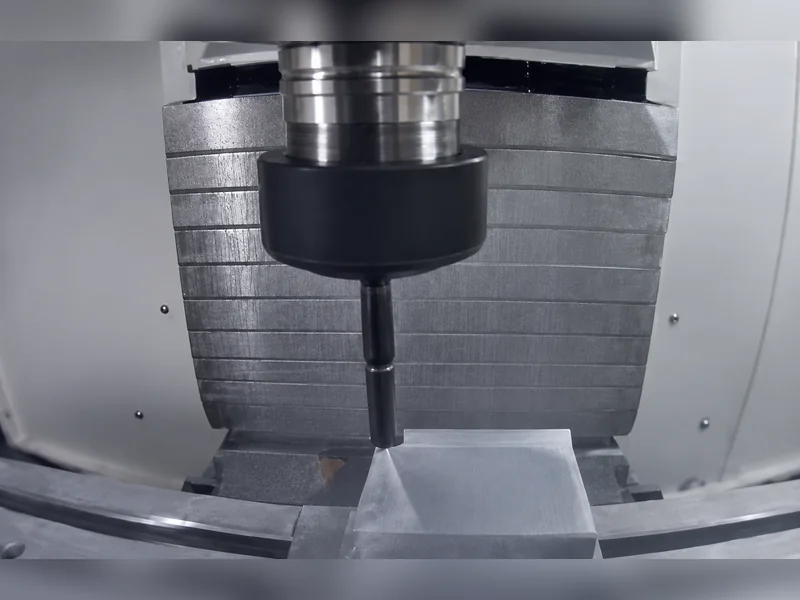
Make a pilot hole that matches the long drill
The pilot establishes the entry path. Its diameter, depth and point geometry should be specified for the particular long drill. A hole made by any available short drill is not necessarily a suitable guide.
A short drill with approximately 2D–3D capacity is one option for the initial guiding stage. Its capacity is not an instruction to drill every pilot to 3D: the long-drill system determines the required pilot depth and tolerance.
The diameter relationship matters. A pilot that is too tight can interfere with entry; excessive clearance reduces its guiding value. Do not improvise a universal allowance of a few microns. Obtain the specified pilot-tool pairing and verify the resulting hole.
Point geometry matters too. If the long drill's outer cutting region contacts the pilot bottom before its center, the initial load can destabilize entry. A suitably larger pilot point angle may help establish the intended contact sequence. Check both tool geometries as a matched pair; a rule for one long-drill system should not be transferred to every spotting or drilling operation.
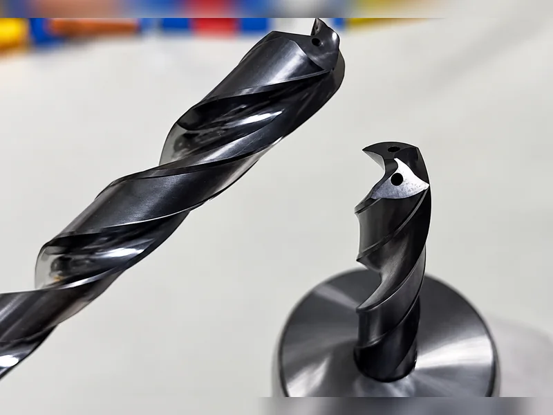
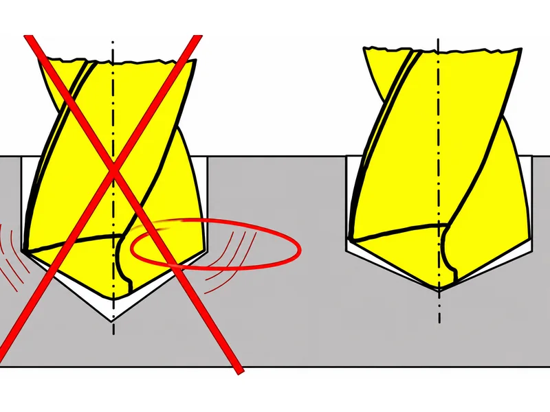
Control entry, cutting and withdrawal as separate parts of the cycle
Introduce the long drill using its specified entry speed and feed. Do not assume that a long unsupported tool should rotate at its normal cutting speed before it is guided.
Reach the specified transition position. Know where the tool is relative to the pilot bottom. Entry into an existing hole and engagement with uncut material are different events.
Apply the prescribed coolant and cutting conditions in the required sequence. Follow the tool-specific timing, spindle speed and feed for the deep-cutting portion.
Withdraw using the recommended routine. Return motion and spindle conditions also belong in the program; the process is not complete when the drill reaches depth.
Keep the pilot specification, entry routine, transition to cutting, pecking instructions and withdrawal routine together as one tool-system procedure. Mixing an entry speed from one drill with the cutting cycle of another leaves the transitions unqualified, even if each setting looks reasonable in isolation.
This is why a deep-hole program needs more than one spindle speed and feed value copied into a cycle. Review the transitions as carefully as the cutting data.
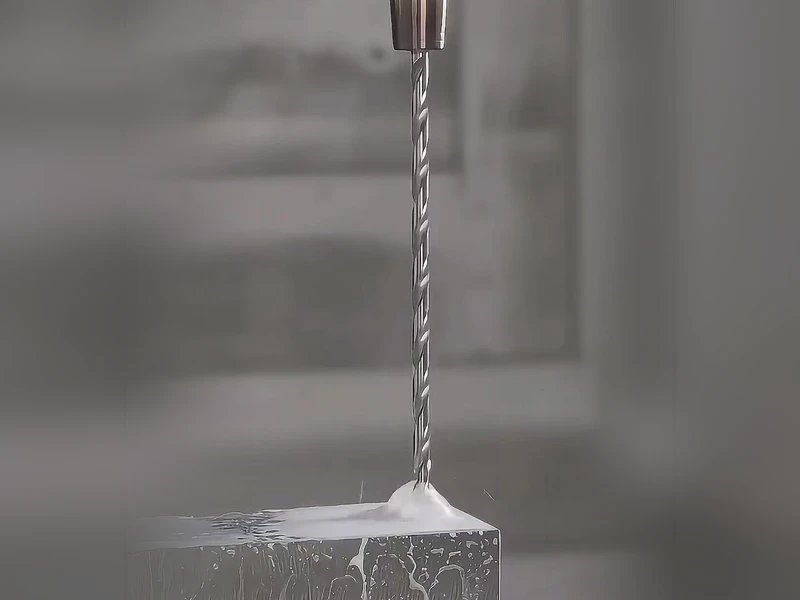
When does an intermediate-length drill help?
For some very long holes, a staged route uses a short pilot, an intermediate drill around 8D–10D, and then the final long drill. The purpose is to create a controlled path in stages rather than ask the longest tool to establish it alone.
That is an application option, not a rule that every hole beyond 20D needs three tools. Some long-drill systems are designed to follow their specified short pilot directly. Adding an intermediate tool introduces another diameter, geometry and alignment relationship that must work with the final drill.
Choose the sequence with the tool supplier against the actual hole and machine conditions. Record the role and transition depth of each tool. If an extra stage is added after a failed trial, state which observed problem it is expected to correct.
Record where the failure occurs before changing the program
The timing of a failure helps focus the next inspection:
Before or during pilot entry: examine the long tool's free length, entry routine, alignment and pilot condition.
At the pilot bottom: review the pilot geometry and the transition into uncut material.
After drilling deeper: investigate chip condition and evacuation, coolant delivery, tool wear and the cutting conditions.
At breakthrough or withdrawal: inspect that portion of the program and the relevant workpiece geometry.
These are investigation directions, not diagnoses from timing alone. Preserve the broken tool and chips, and record the depth and cycle position. Change a clearly identified factor, then compare the next trial under recorded conditions.
For a wider investigation beyond the long-drill sequence, see our guide to drill-breakage root causes. For this process, the first practical improvement is often to make the order explicit: suitable pilot, controlled entry, qualified coolant and cutting conditions, then controlled exit. Verify the finished hole against the drawing before calling that sequence successful.
For the tool family discussed here, review our solid carbide drills and deep-hole drill options. Confirm the pilot pairing, usable depth and entry procedure for the actual tool before programming.
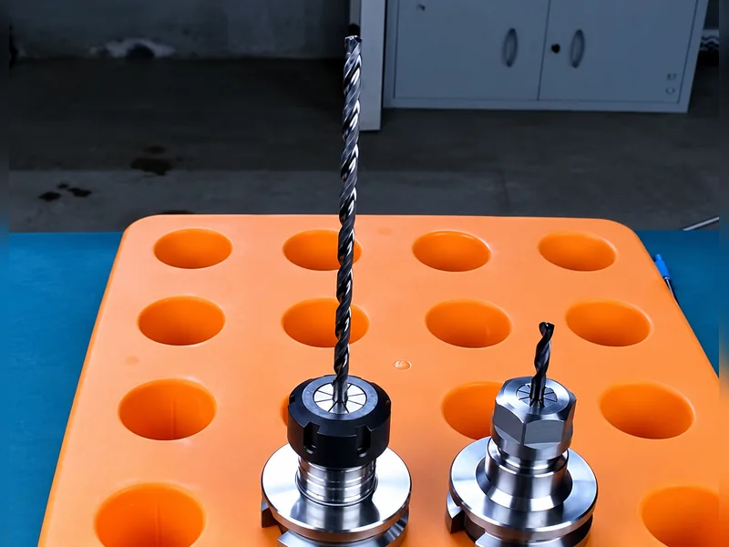
Process video supplied with this article. Apply the selected tool system’s instructions to the actual machining conditions.