

Drilling Burr Formation or Chip Scratches? Check the Hole Edge First
A drilling burr is attached workpiece material that projects from an edge. A groove or indentation on the nearby face or inside the hole is a different defect and calls for a surface-contact inspection. If both are present, investigate both: removing the raised edge does not repair the scratched surface.
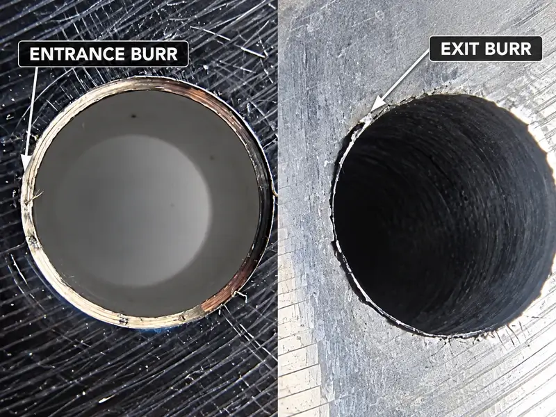
That distinction comes before choosing a larger chamfer, changing the drill point or reducing feed. Chip contact is one possible source of damage, but neither a circular mark nor its location proves what caused it. The useful question is: what changed at the edge, on the surrounding face and along the hole wall—and when?
Map the defect before removing it
Preserve the as-drilled condition first. With the machine safely stopped and access permitted by the site's procedures, photograph the entrance, exit and any retained chips before cleaning or deburring. Do not feel a sharp edge with a bare finger or reach for hot chips. Remove loose swarf only by the approved method, without scraping away the feature you need to inspect.
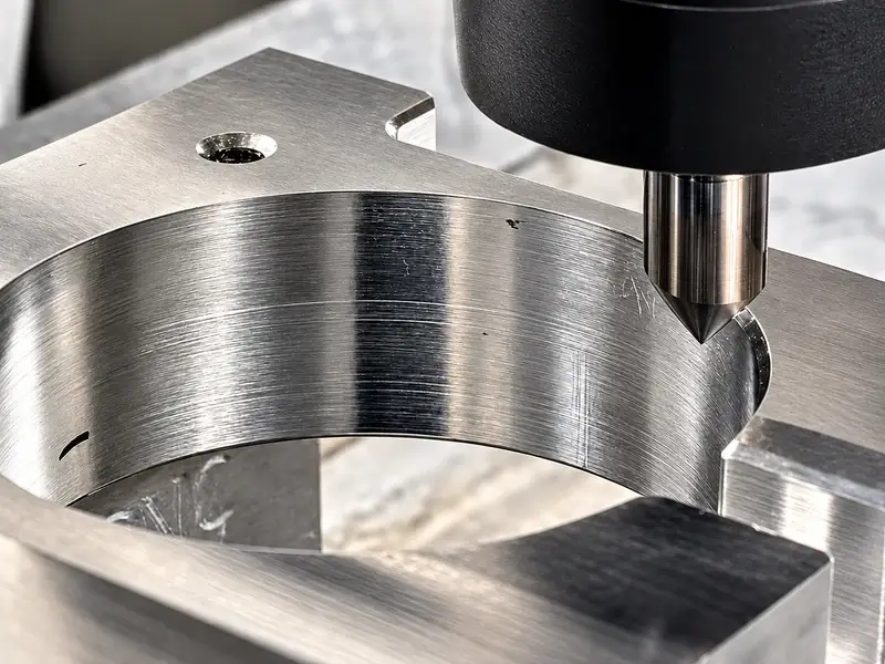
Label the drill entrance and exit, the face beside each opening, and the hole wall. These are different inspection locations. A mark beside the entrance is not necessarily an entrance burr; a line inside the bore is not the same feature as a raised exit edge.
Use suitable magnification and, where needed, a profile or dimensional measurement to establish whether material projects above the local surface or has been indented or removed. A burr may be irregular rather than a complete ring. Raised material beside a scratch also needs examination: its presence alone does not establish that the original drilling edge formed a burr.
| What you can establish | First inspection branch | Evidence to seek next |
|---|---|---|
| Attached material projects from the hole edge | Burr formation at that entrance or exit | Edge condition, stability and support, together with the phase in which the projection appears |
| Grooves or indentations affect the adjacent face or hole wall | Contact damage, including possible chip contact | Retained swarf, a restricted escape path and evidence of contact during the relevant motion |
| Edge projections and surface damage occur together | Keep both branches open | Separate records of edge height/profile and neighboring surface damage, before and after any correction |
This is a way to choose inspections, not a visual root-cause test. Establish the requirement too. Does the drawing call for a controlled edge, an undamaged seating face, a specified bore finish, or several of these? “Make it shiny” does not tell the operator which feature must be corrected or give quality staff an acceptance criterion.
Find out when the damage is added
Use the program sequence, permitted inspection opportunities and approved observation methods to relate the defect to the machining cycle. Any staged trial must be planned for the machine and tooling; do not bypass safeguards or improvise access while the tool is engaged.
If the projection is already present after initial entry, inspect the entry surface, cutting edge and setup stability. If the exit edge changes at breakthrough, examine the exit condition and support as well as the drill condition and cutting data. These timings direct attention; they do not rule out damage that began earlier.
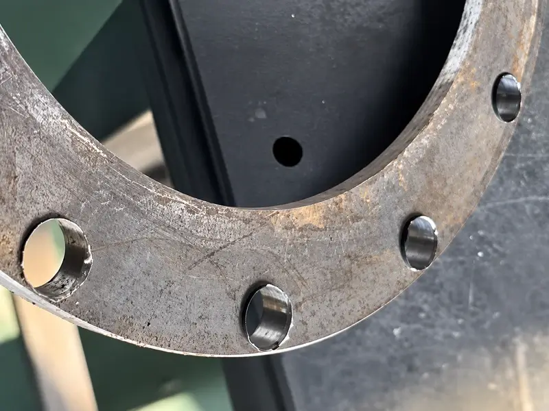
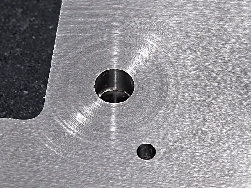
For marks that appear or increase after withdrawal or a later re-entry, follow the chips around the opening. Check whether swarf remains at the mouth after the tool retracts. Where a fixture surrounds the opening, look for a pocket that retains chips and a possible path by which the next motion could carry them back into contact. Check whether the coolant actually carries the chips away or merely moves them to another trapped location.
Do not condemn a surrounding fixture simply because it is there. Retained chips, contact evidence and the timing of new marks should support the hypothesis. Likewise, a curved scratch does not distinguish chip contact from direct tool contact, fixture contact or marks added by deburring. If the mark existed before drilling, return to the preceding operation instead of tuning the drill to cure it.
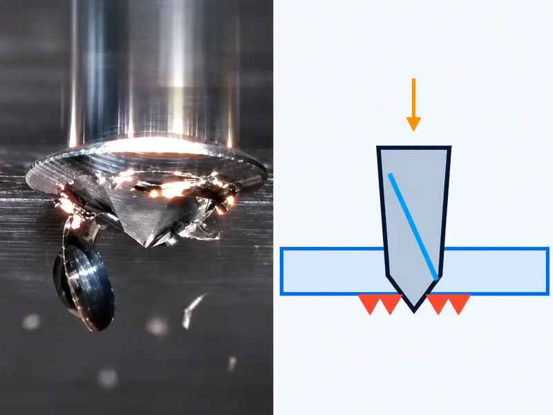
Follow the branch the evidence supports
When attached edge material is the main defect
Inspect the drill's cutting edges for wear, damage and adhered material. Check workpiece and toolholding stability, and investigate alignment or runout where unequal contact or the hole measurements point to it. For exit burrs, examine the actual breakthrough condition and available support rather than assuming that every exit needs the same program change.
Correct an observed problem first: a damaged edge, unstable clamping or an unsuitable entry or exit condition. If the evidence instead calls for a cutting-data or geometry trial, use guidance for the exact drill, material and hole. Drilling burr formation depends on the combination of these conditions; it is not a point-angle contest. The point, cutting edges, flutes and supporting drill geometry work together.
A blanket instruction to reduce feed can therefore miss the problem. Define what the proposed change is intended to improve, keep it within the tool's operating guidance, and check the resulting edge and chip behavior. Do not accept a smaller visible burr if the hole or surrounding surface has become unacceptable.
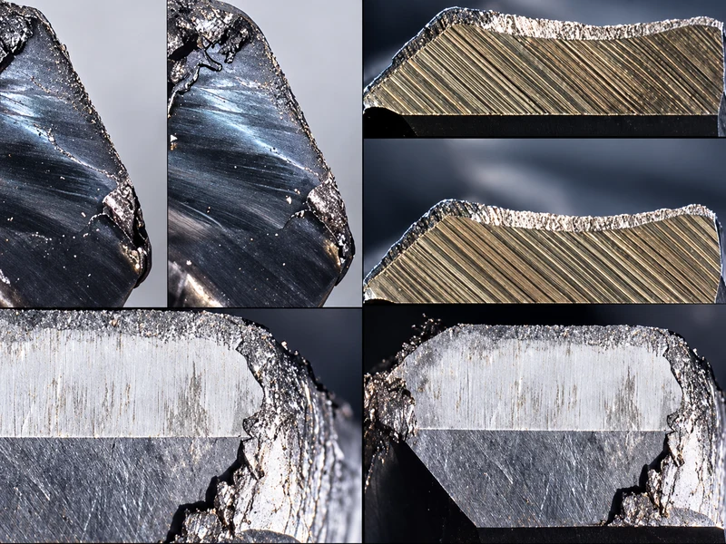
When chip contact is supported
Inspect both the chips and their escape route. Record length, width, curl, nesting and any wrapping, then check what remains in the flute, at the mouth and around the fixture. A narrower chip is not necessarily a short, broken chip, and chips visible outside the hole do not prove that the route stays clear throughout the cycle.
Address the restriction you can identify. That may mean restoring an obstructed coolant path, correcting an approved nozzle arrangement, clearing a chip-retaining area or having the fixture's chip clearance reviewed. Confirm the result at the actual opening and cutting zone, not just by checking that the pump is on. Do not alter a clamp or fixture clearance without preserving its workholding function.
If chip form or the withdrawal/re-entry motion remains the issue, review the cycle and tool choice against the toolmaker's instructions for that application. Where a pecking cycle adds repeated entry, use the peck-drilling re-entry checks to examine that motion separately. This is a controlled process decision, not a reason to grind improvised grooves into a drill.
In their 2019 study, “The effect of interlayer gap width on burr formation in drilling of aluminium-aluminium aerospace stacks”, Pardo and colleagues examined sealed aluminium-aluminium stacks. They observed swarf and small scratches near the interlayer hole edges and interpreted them as evidence of chips entering the gap and being dragged by the rotating drill. They also observed abrasion and edge rounding where little conventional burr remained. That stacked-interface result does not prove the cause at an exposed hole mouth; it shows why “less burr” alone cannot certify intact edge geometry.
If the inspection also finds chipped or broken tooling, expand the investigation using the drill-breakage root-cause guide. A damaged drill needs its own cause checked, not merely its visible chips cleared away.
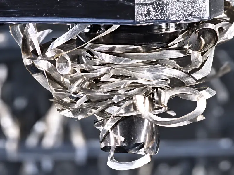
Close the trial on geometry, not shine
Before changing the process, retain a baseline record of the material, drill identity and condition, hole geometry, fixture, cycle and coolant arrangement. Mark the defect locations on the photographs. Then make one evidence-supported correction so that the result remains interpretable.
Inspect the trial hole at the same locations, with the same method used for the baseline:
Check attached projections at both entrance and exit, not just the more accessible side.
Check the adjacent faces for remaining grooves, indentations or unintended edge rounding.
Check the hole wall and required dimensions or surface finish.
Check where chips remain after the cycle, particularly before any subsequent re-entry.
If deburring is part of the approved process, inspect again afterward. Removing a projection may leave a groove untouched; enlarging a chamfer may conceal the edge of a damaged face without restoring it. Rework or part disposition must follow the drawing and the responsible quality process.
An acceptable trial hole is a checkpoint, not proof of stable production. Continue verification to the site's control plan and keep the record of the defect, the supported cause, the change and the measurements. The next operator should be able to see what improved—and which edge and surface requirements were actually met.