



Machining Tungsten Carbide Before Sintering with PCD Tools
PCD tools can be used to machine tungsten carbide before sintering. The important condition is before sintering: you are shaping a pressed powder body, not cutting the finished, dense cemented carbide. That distinction changes how the part is supported, which defects matter and when its dimensions can be accepted.
Use this route to form features that belong in the compact, with the material producer's shrinkage control and any later finishing allowance built into the drawing. If the component is already fully sintered, assess that condition separately before carrying over a PCD recommendation.
Why consider PCD before sintering?
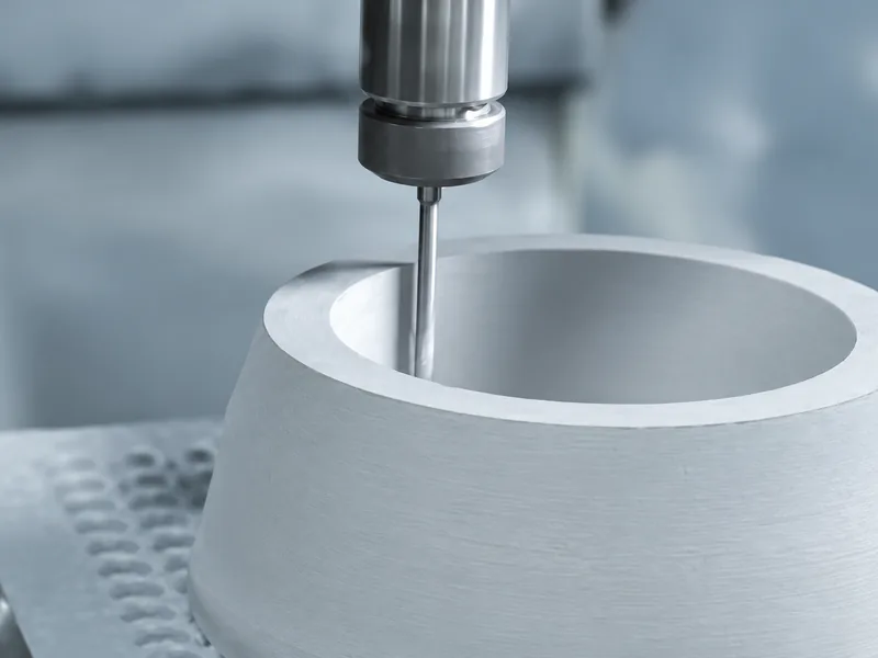
PCD cutting edges are used in tools for machining unsintered carbide compacts. Their wear resistance is a reason to evaluate them for repeat work in abrasive material. But edge life and part integrity must be considered together: a wear-resistant tool is useful only if the compact survives the cut with the required feature intact.
Confirm the compact and its manufacturing stage
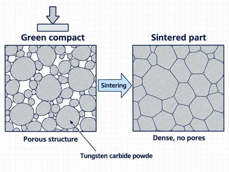
A pressed powder body that has not yet been sintered is called a green compact in powder metallurgy. Here, “green” describes its manufacturing state, not its colour or environmental credentials. Its handling and cutting behaviour differ from those of the dense component. This is why a feature may be practical to machine now but require a different finishing route later.
The sample and production blanks must represent the same condition. A successful cut on one processing state is not evidence for another.
Decide which dimensions belong to which stage
Sintering changes the size of the compact. The machining drawing for the unsintered part must therefore connect to the intended sintered dimensions through the material producer's shrinkage control. Applying the finished-part dimensions directly to the unsintered blank can produce an accurately machined part that becomes the wrong size later.
Separate the requirements into three groups:
Features to create now: the holes, profiles or surfaces included in the machining operation before sintering.
Material to retain: any allowance needed for later finishing or for control of the sintered shape.
Requirements to verify later: the dimensions and surfaces that become meaningful only after sintering and any specified finishing.
A hole that will be finished after sintering and a hole intended to emerge directly within its final tolerance are different tasks. That difference should be explicit before the tool for this operation is designed. Obtain the shrinkage basis for the actual grade and manufacturing process.
Choose the features and support before choosing cutting data
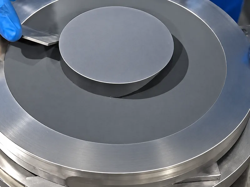
For each planned hole, profile or recess, identify the least-supported part of the feature before deciding how to cut it.
Examine how the compact will carry the cutting load. A thin wall between a hole and the outside profile has less support than the bulk of the blank. A corner at cutter exit can break away even when the preceding surface looks satisfactory. Increasing clamping force can also damage a compact instead of stabilising it.
Use the feature that is most difficult to support to plan the cut. Establish support close enough to resist the load without marking the part, and check what happens when the edge enters and leaves the feature. Keep necessary stock for later operations rather than judging every surface against the final drawing immediately.
| What the first cut shows | What to investigate next | Why it changes the decision |
|---|---|---|
| The tool cuts, but an exit corner breaks away. | Local support, exit engagement and cutting-edge condition. | Tool survival alone does not establish a usable machining route. |
| Marks or cracks appear at the clamping contacts. | Contact area, support and clamping load. | The workholding may be damaging the compact before cutting quality becomes the limiting factor. |
| Dimensions before sintering repeat, but sintered dimensions do not. | Batch identity, thermal history and shrinkage control with the material producer. | Changing the cutting program first can conceal a downstream source of variation. |
| The PCD edge chips while the compact remains supported. | Entry, interruptions, edge geometry and assembly stability. | A harder cutting material or a coating name does not resolve an impact or instability problem by itself. |
Use these diagnostic situations to record the feature and defect during a trial. That record explains what needs changing far better than a result labelled only “PCD worked” or “PCD failed.”
What the PCD recommendation must specify
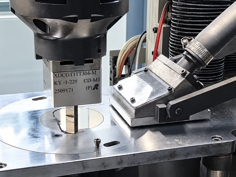
A useful recommendation identifies the compact's grade and condition, the operation, the cutting edge and the setup together. “PCD” identifies a cutting material; it does not define the rake, edge preparation, projection or entry that this particular part needs.
Give the tool engineer the feature drawing, stock allowance, support arrangement and any interrupted engagement. If a previous tool failed, distinguish progressive wear from edge chipping and show where damage began. That evidence gives the next design a purpose: maintain an edge, reduce a damaging entry or support a vulnerable feature.
Progressive wear and impact chipping call for different design responses. Develop cutting data for the actual compact and operation rather than carrying over values from dense carbide or a different thermal condition.
Judge the part before and after sintering
Check the dimensions of the unsintered part, edges and clamping contacts immediately after machining. Keep the material batch, manufacturing state, tool condition and setup with those results. Then follow the same identified parts through sintering and any planned finishing.
The later check answers a different question: did the complete route produce the required dimensions and surfaces? A feature in the unsintered part can pass its own drawing and still fail after an uncontrolled downstream change. Conversely, a final inspection alone can hide where a defect first appeared. Keeping both measurements lets the team correct the right operation.
Agree the acceptance limits and trial stopping conditions before cutting. Repeated acceptable parts, their required finishing and tool consumption are the basis for evaluating production, rather than a single demonstration that the edge can remove material.
Keep feasibility separate from a production commitment
A PCD route may be technically workable but uneconomic for a particular order. Development, fixture preparation and trial time matter, especially for small quantities. Establish whether the part is a one-off, a repeat order or an ongoing consumption requirement before treating custom-tool development as a routine purchase.
The same distinction applies when a supplier declines the work. A lack of relevant equipment or experience is a limitation of that supplier's proposed route, not proof that the material cannot be machined.
Fully sintered carbide needs its own process assessment. PCD is used in some applications, while others call for grinding or another finishing route; the trial before sintering does not decide that choice.
For a proposal to machine the unsintered compact with PCD, start with the confirmed material state and the feature to be made. Decide what belongs before sintering, support the compact through the cut, and retain the measurements that connect it to the finished part. That sequence makes tool selection an engineering decision with a result the shop can check.
For the tooling discussion, see our PCD turning inserts and custom PCD tools. Send the compact grade, manufacturing state and tool or workpiece drawing so we can assess the cutting edge and support needed for your operation.
For background on shaping and sintering cemented carbides, see the International Tungsten Industry Association’s technical overview.