


Ra surface finish: what 1.6, 0.4 and 0.2 µm mean for machining
In Sunditools' application practice, Ra 1.6 µm prompts a process question: can the existing operation maintain the finish, or does it need a finishing step? Around Ra 0.4 µm, the question becomes whether the complete setup has demonstrated that capability. At Ra 0.2 µm, clarify the required result and the permitted finishing route rather than assuming that a brighter surface or a different cutter will be enough.
These are practical review points from our experience, not standard boundaries between possible and impossible machining. A new tool producing one good surface is a different result from a process that keeps meeting the drawing as the edge wears.
Read the requirement before choosing the process
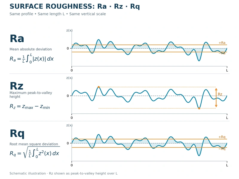
Ra describes the average roughness of a measured surface profile. A lower value means a lower average deviation from the profile's mean line. It does not, by itself, tell you which cutter to buy or whether a part will look like a mirror.
Confirm the parameter and unit on the drawing. Ra, Rz and Rq describe different aspects of a surface; do not substitute one for another. The values in this article are Ra in micrometres, written µm. A value specified in microinches is not the same numerical requirement.
NIST's surface parameter reference defines Ra using the average absolute profile-height deviation. That definition explains why Ra is useful for reporting roughness, but it does not make Ra a complete description of the surface.
Identify the surface to which the requirement applies. A bore wall, a milled sealing face and an accessible turned diameter can carry the same Ra callout while requiring different tools and inspection arrangements. Also establish whether the surface must be produced directly by cutting or whether a subsequent operation, such as honing or polishing, is allowed.
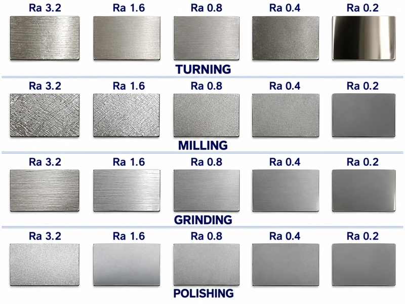
The following table is a planning guide, not a chart of guaranteed tool capabilities.
| Specified finish | What to resolve before committing to the job |
|---|---|
| Ra 3.2 µm | Can the proposed operation meet this requirement on the actual material, feature and setup? Do not assume every drilled or milled surface will pass. |
| Ra 1.6 µm | Is the existing operation consistently good enough, or should the process include a controlled finishing pass or finishing tool? |
| Ra 0.8 µm | What changes in geometry, support, edge condition and process control are needed beyond the established baseline? |
| Ra 0.4 µm | What measured evidence shows that the complete machining system can sustain this finish? |
| Ra 0.2 µm | Can the proposed direct-cutting process be validated, or is a different finishing route needed and permitted? |
Read any other drawing requirements alongside Ra. A low roughness result does not establish bore size, roundness, cylindricity or flatness. Those remain separate acceptance requirements.
At Ra 1.6 µm, reconsider the finishing operation
The first decision is whether the operation selected for material removal is also suitable for the final surface. Reaching Ra 1.6 µm once does not answer that question.
Our internal training uses aluminium holemaking to illustrate the distinction. It describes drilling around Ra 3.2 µm as a familiar starting expectation in some applications, with a particularly sharp new drill sometimes producing Ra 1.6 µm on the first holes. It also discusses reaming results in the approximate Ra 0.4 to 1.6 µm range. These are application observations, not a specification for every aluminium grade, drill or reamer. Their usefulness is in comparing process choices; they do not establish a rated tool capability.
Compare the production routes, not just their best samples. If a drill passes the finish requirement only when new, repeatedly lowering feed or changing a tool early may be the wrong production strategy. Compare that route with a finishing operation, including its extra cycle time, tooling and inspection needs.
For a milled surface, examine the finish pass as a process: the stock it receives, how the part is supported, the cutting edge condition and whether the tool can cut the intended allowance consistently. Our guide to finishing milling covers those operating decisions in more detail.
The number alone does not require a separate finishing tool. A proven existing process may already be sufficient. The Ra 1.6 review point is a prompt to check that evidence before assuming the roughing or drilling operation will also deliver the final surface.
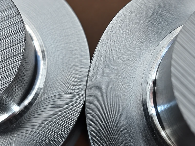
At Ra 0.4 µm, prove capability before committing
At this stage, tool selection needs to be considered together with the machine, holder, workholding, reach, material and coolant delivery. Replacing the cutter while leaving an unstable setup unchanged is not a capability demonstration.
Start with the actual material grade and condition. Our training distinguishes aluminium, cast iron, and steel or stainless steel because a process that gives a fine finish in one cannot simply be transferred to another. It treats fine finishes in cast iron as a reason to examine finishing geometry and rigidity closely. It also warns against promising a very fine finish from an ordinary milling setup in steel without testing it. The achievable result still depends on the selected process and its demonstrated performance.
For a bore, consider how the cutting edge and guiding features interact with the prehole. In suitable applications, a purpose-designed PCD reamer may combine cutting with a controlled guiding or burnishing action. That is a tool-and-application decision: it depends on material compatibility, geometry, allowance and the required hole quality. Specifying PCD on its own does not establish Ra 0.4 µm capability.
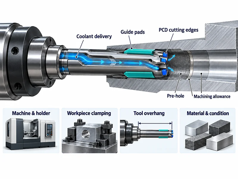
Check the complete assembly and the stock left by the previous operation before attributing an unsuccessful trial to the tool material. If the trial already shows chatter, rubbing or built-up edge, use the relevant reaming surface finish diagnosis to investigate the defect. Here, the planning decision is whether the proposed route is ready to support a production commitment.
Record which conditions produced the acceptable finish. If the result depends on a short, rigid setup and a particular material condition, those conditions belong with the result. A sample made with easy access does not establish capability for the same diameter at a much longer reach.
Ra 0.2 µm and mirror finish are different requirements
As the requested Ra falls, it becomes more important to distinguish a numerical surface requirement from an appearance requirement. A customer asking for a mirror may mean a bright reflection, a clear reflected image or an optical component with defined performance. Those are not interchangeable specifications.
Our internal discussion contrasts the visibly reflective finish that some PCD applications can produce with the more demanding optical finish associated with suitable single-crystal diamond machining systems. PCD means polycrystalline diamond; MCD is used here for monocrystalline, or single-crystal diamond. These tool descriptions are not grades of mirror quality.
Specialized diamond turning uses a precision system designed for optical manufacture. It is not equivalent to installing a diamond edge on an ordinary machine. Very low Ra requests therefore need a review of the proposed setup and process, rather than an assumed lower limit for all cutting tools.
For Ra 0.2 µm, establish what the part actually needs and what route is allowed. If the proposed machining process has not demonstrated the result, do not present honing or polishing as an automatic solution. Confirm that a secondary process is permitted and assess its effect on the other drawing requirements. If direct machining is required, the trial must demonstrate that route.
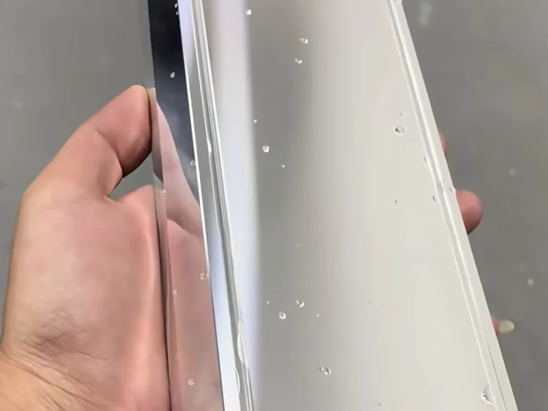
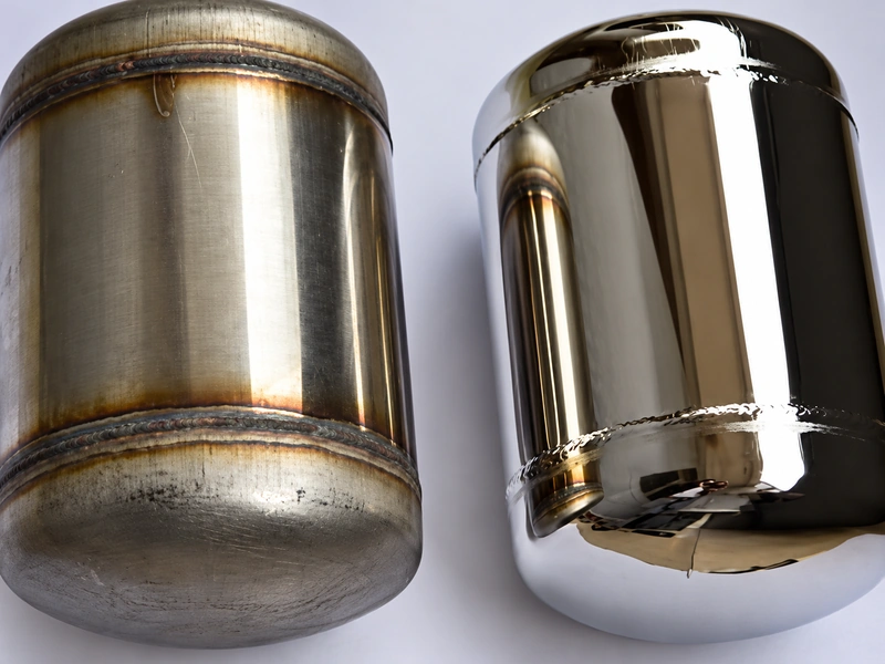
A bright surface is useful visual evidence, but it is not an Ra measurement. Equally, a low Ra reading does not prove optical quality.
Verify the finish over the intended production run
Agree how the surface will be measured before comparing trials. Record the instrument and relevant settings, including cutoff and evaluation length, together with the measurement direction and locations. Follow the drawing and applicable measurement procedure. Measurement direction relative to the surface lay affects the result; the NPL guide to stylus surface measurement explains this and why surfaces with similar Ra can still have different functional characteristics. It is a metrology reference, not a machining capability chart.
Visual inspection can locate scratches, torn areas or repeating marks that deserve investigation. Touch cannot assign a reliable numerical Ra value. Do not accept a surface simply because it looks bright or feels smooth.
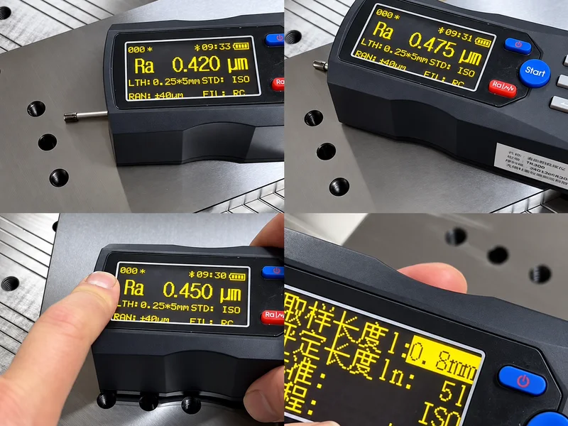
Then test the production claim you intend to make. Measure representative parts as the tool progresses through the intended run, rather than reporting only the best new-tool sample. Keep material, geometry, setup and measurement conditions traceable. Record both acceptable results and departures from the requirement, including where on the feature they occurred.
Set the sampling and acceptance plan for the part's requirements and risk. Choose trial quantities to support the production claim and the agreed acceptance plan. If the evidence covers only a short run, describe it as a short-run result. If a process change is needed, compare the revised route under controlled conditions before extending the claim.
Commit to the process you have demonstrated
Before promising the finish, connect three things: the drawing requirement, the permitted process route and the results over the intended run. The 1.6 and 0.4 µm review points help decide where to investigate; they cannot replace that evidence. Keep size, form and any optical requirements separate from the Ra result.
If the finish is acceptable on the first parts but drifts later, discuss the application with our engineering team using those measurements—not only the best sample. Include the material, feature, tool reach and whether a secondary finishing operation is allowed. Those details let Sunditools assess tool geometry, cutting tool material and cutting parameters within the process you actually need to run.
For the tool families discussed here, explore our carbide reamers and customized carbide reamers. Tool selection still requires the workpiece, geometry and measured trial conditions.